
Luminance-chrominance calibration production line of LED display module

a technology of led display module and chromium, which is applied in the field of display correction/calibration technology, can solve the problems of time-consuming and laborious calibration, difficult to meet the requirements of a large number of shipments for the display screen manufacturer, and time-consuming manual calibration, so as to relieve even elimination of inaccurate data collection/acquisition, increase the calibration efficiency, and improve the effect of efficiency

Active Publication Date: 2017-08-17
XIAN NOVASTAR TECH
View PDF10 Cites 0 Cited by
  • Summary
  • Abstract
  • Description
  • Claims
  • Application Information

AI Technical Summary

Benefits of technology

The invention describes a method that uses multiple image acquisition devices to collect color information from LED display modules simultaneously, improving calibration efficiency and accuracy. This method also reduces the need for manual placement of the LED display module and automates the calibration process, saving time and money.

Problems solved by technology

However, these display screens more or less have the problem of non-uniform display such as mosaic caused by deviation / difference of luminance and / or chrominance between LED dots, and thus it is necessary to calibrate each LED dot with the help of image acquisition apparatus so as to make the displays of the LED display screens are as smooth as mirror.
However, the existing cabinet calibration is time-consuming and requires a lot of labor, and therefore it is difficult to meet the requirements of a large number of shipments for the display screen manufacturers.
From the foregoing discussion, it can be understood that in the conventional LED cabinet calibration method in the factory, the LED cabinet is manually placed onto the preset position, if the placed position and the preset position have an offset existed therebetween, which will affect the data acquisition / collection for the LED cabinet; moreover, it cannot perform image acquisition simultaneously to multiple LED cabinets; and in addition, it needs two persons for carrying the cabinet and one calibration operation person, the co-working of three persons leads to the manual calibration being time-consuming.

Method used


Image

  • Luminance-chrominance calibration production line of LED display module
  • Luminance-chrominance calibration production line of LED display module
  • Luminance-chrominance calibration production line of LED display module

Examples


Embodiment Construction

[0026]In order to make the above objectives, features and advantages of the invention be more apparent, concrete embodiments of the invention will be described below in detail with reference to the accompanying drawings.

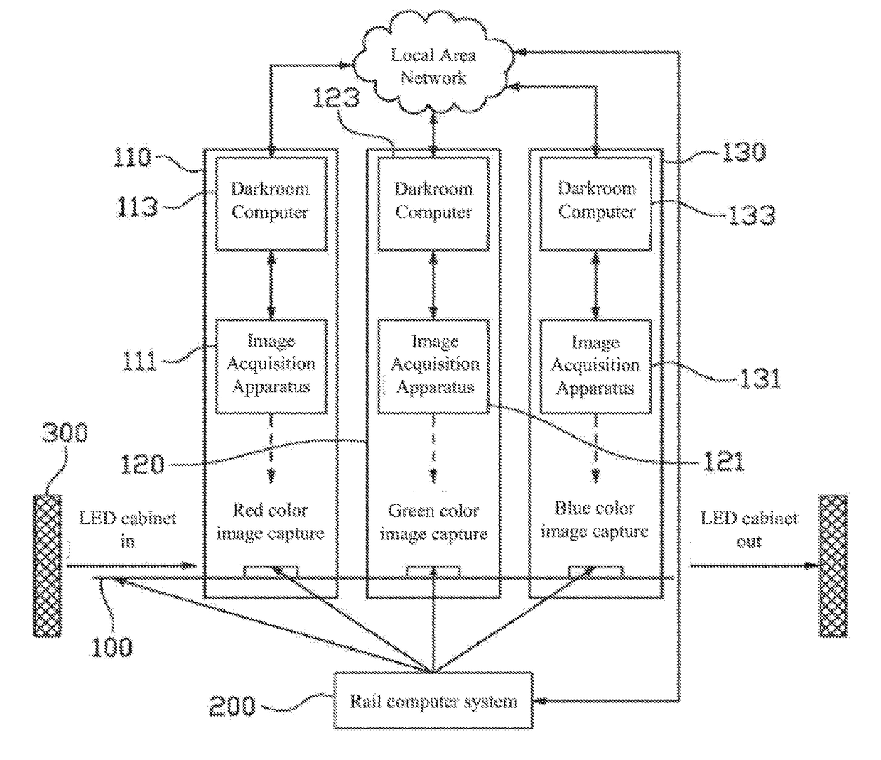
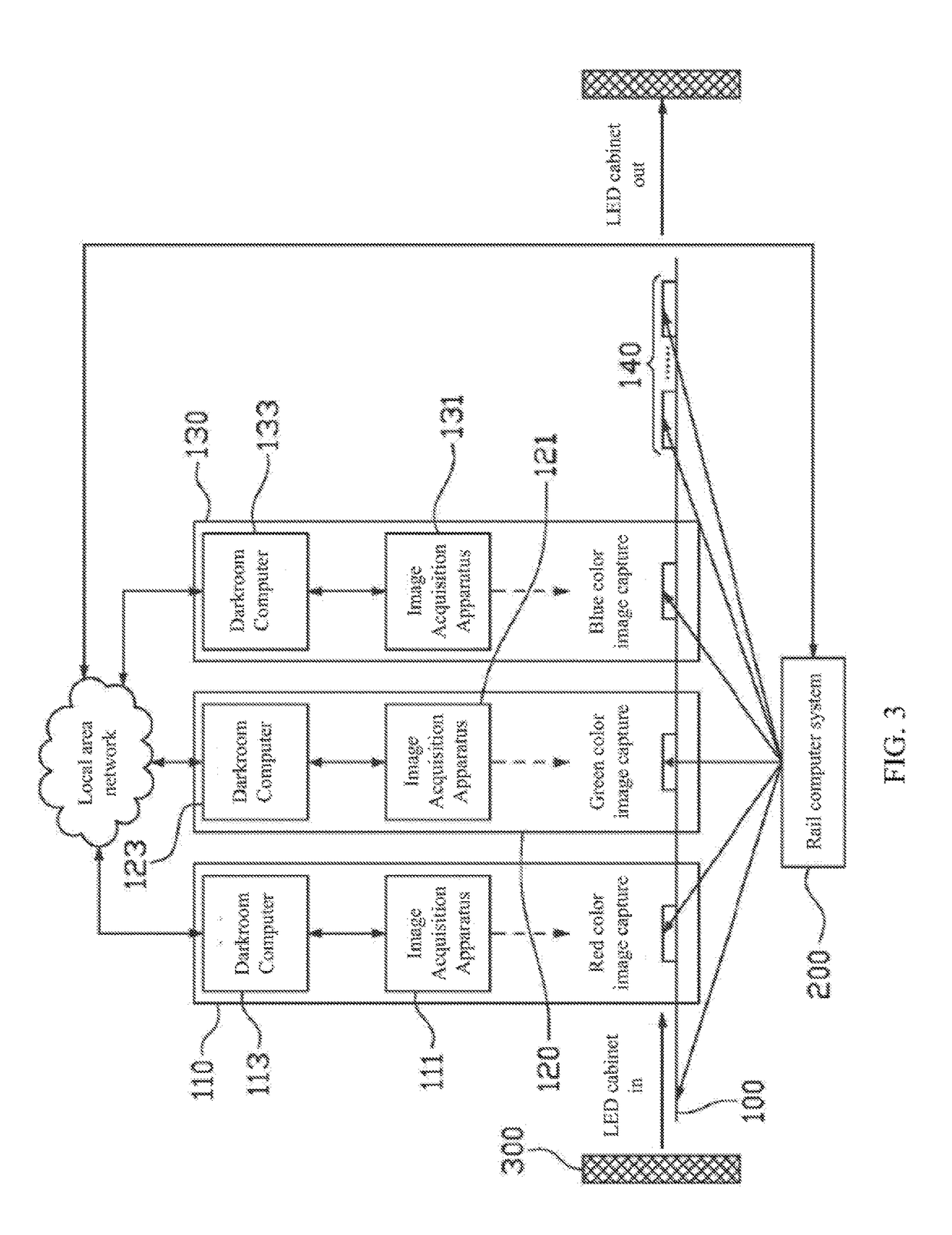
[0027]Referring to FIG. 2, a systematic architecture of a luminance-chrominance calibration production line of LED display module according to an embodiment of the invention is shown. As illustrated in FIG. 2, the luminance-chrominance calibration production line of LED display module includes: a rail 100; a plurality of darkroom stations 110, 120, 130 disposed along the rail 100; image acquisition apparatuses 111, 121, 131; darkroom computers 113, 123, 133; and a rail computer system 200.

[0028]The image acquisition apparatuses 111, 121, 131 respectively are disposed in the darkroom stations 110, 120, 130. The darkroom computers 113, 123, 133 respectively are signally connected with the image acquisition apparatuses 111, 121, 131 in the respective darkroom stations 1...


PUM


Abstract

A luminance-chrominance calibration production line system includes: a rail; multiple stations disposed along the rail and including multiple first darkroom stations; multiple image acquisition apparatuses respectively disposed in the first darkroom stations and for capturing different color images sequentially displayed by a to-be-calibrated LED display module loaded on the rail to acquire color image data; and a rail computer system for controlling a transport movement on the rail and controlling the to-be-calibrated LED display module to display the different color images, and being signally connected to the image acquisition apparatuses to obtain the color image data. By using multiple image acquisition apparatuses to collect various color image information of LED display module in pipelined manner, calibration efficiency is improved, data collection is accurate, data collection error caused by using different image acquisition apparatuses to calibrate different LED display modules is avoided and calibration manpower is reduced.

Description

CROSS-REFERENCE TO RELATED APPLICATIONS[0001]This application is a divisional application of U.S. patent application Ser. No. 14 / 740,164, filed on Jun. 15, 2015, which is a continuation of PCT International Application No. PCT / CN2015 / 070715, filed on Jan. 14, 2015, which claims the priority of Chinese Patent Application No. 201410289321.8, filed on Jun. 24, 2014, the disclosure of which is incorporated herein by reference in its entirety.FIELD OF THE INVENTION[0002]The invention relates to the field of display correction / calibration technology, and more particularly to a luminance-chrominance calibration production line of LED (light emitting diode) display module.BACKGROUND OF THE INVENTION[0003]With the development of LED display industry, the LED display screens are widely used in more and more occasions such as advertisement, traffic, dispatch center, shows and rally. However, these display screens more or less have the problem of non-uniform display such as mosaic caused by dev...

Claims


Application Information

Patent Timeline
Patent Type & Authority Applications(United States)
IPC IPC(8): G06T7/00G06T7/90G09G3/32
CPCG06T7/001G09G3/32G09G2320/0693G06T2207/10024G06T7/90G09G2320/0233G09G2320/0242G09G2300/04
Inventor ZHAO, XINGMEI
Owner XIAN NOVASTAR TECH
Learn More