Image Forming Apparatus, Photoreceptor Unit, and Transfer Belt Unit

a technology of image forming apparatus and photoreceptor, which is applied in the direction of electrographic process apparatus, optics, instruments, etc., can solve the problems of reducing the image quality, reducing the effect of promoting the deterioration of the photoreceptor, so as to prevent the generation of discharge at the transfer section, the effect of reducing the light entering the squeeze nip portion and preventing the deterioration of the image quality

Inactive Publication Date: 2010-03-18
SEIKO EPSON CORP
View PDF26 Cites 6 Cited by
  • Summary
  • Abstract
  • Description
  • Claims
  • Application Information

AI Technical Summary

Benefits of technology

[0026]According to the image forming apparatus, the photoreceptor unit, and the transfer belt unit of these aspects of the invention, generation of discharge at the transfer section can be prevented by providing the electrification reducing light source. Thus, deterioration of the image quality and the latent image carrier can be prevented. Moreover, light entering the squeeze nip portion is reduced by the reflection preventing member as well as the function of the electrification reducing light source. Thus, appropriate potential difference can be maintained between the non image part on the latent image carrier on the photoreceptor and the squeeze roller. Accordingly, unnecessary fog toner can be efficiently removed from the non image part, and lowering of the image quality caused by decreased whiteness of the white portion on the sheet can be prevented.

Problems solved by technology

When the potential difference produced between the photoreceptor surface voltage and the intermediate transfer member voltage is excessively large, electric discharge is generated therebetween.
This discharge causes image distortion, and thus lowers the image quality.
Moreover, the discharge generated at the transfer section produces a discharge trace on the photoreceptor, and promotes deterioration of the photoreceptor.
In this case, desired potential difference cannot be produced between the second photoreceptor squeeze roller 13′ and the non image part, and fog toner cannot be accurately removed.
When fog toner at the non image part is not properly removed, whiteness of the white part of the sheet decreases.

Method used


Image

  • Image Forming Apparatus, Photoreceptor Unit, and Transfer Belt Unit
  • Image Forming Apparatus, Photoreceptor Unit, and Transfer Belt Unit
  • Image Forming Apparatus, Photoreceptor Unit, and Transfer Belt Unit

Examples


Embodiment Construction

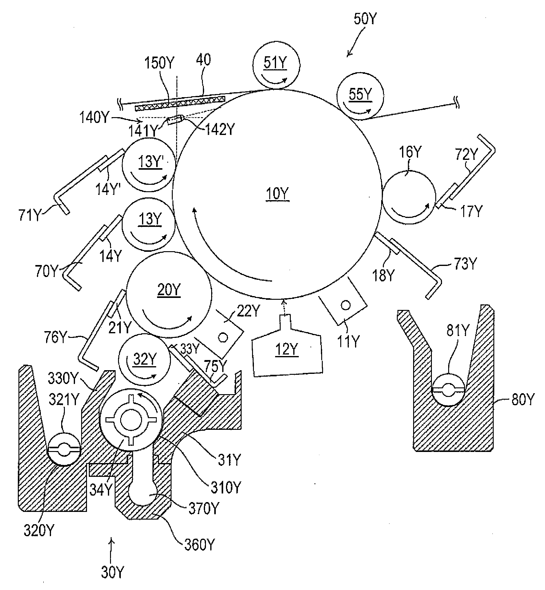
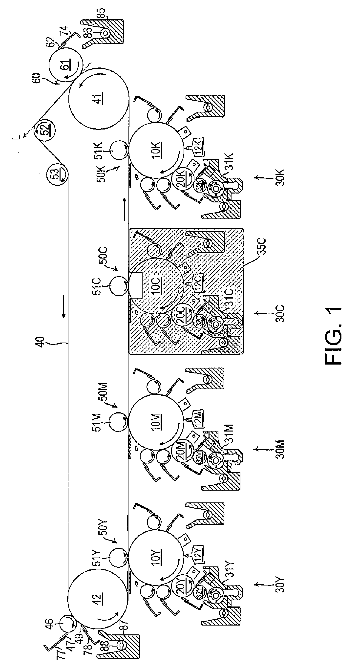
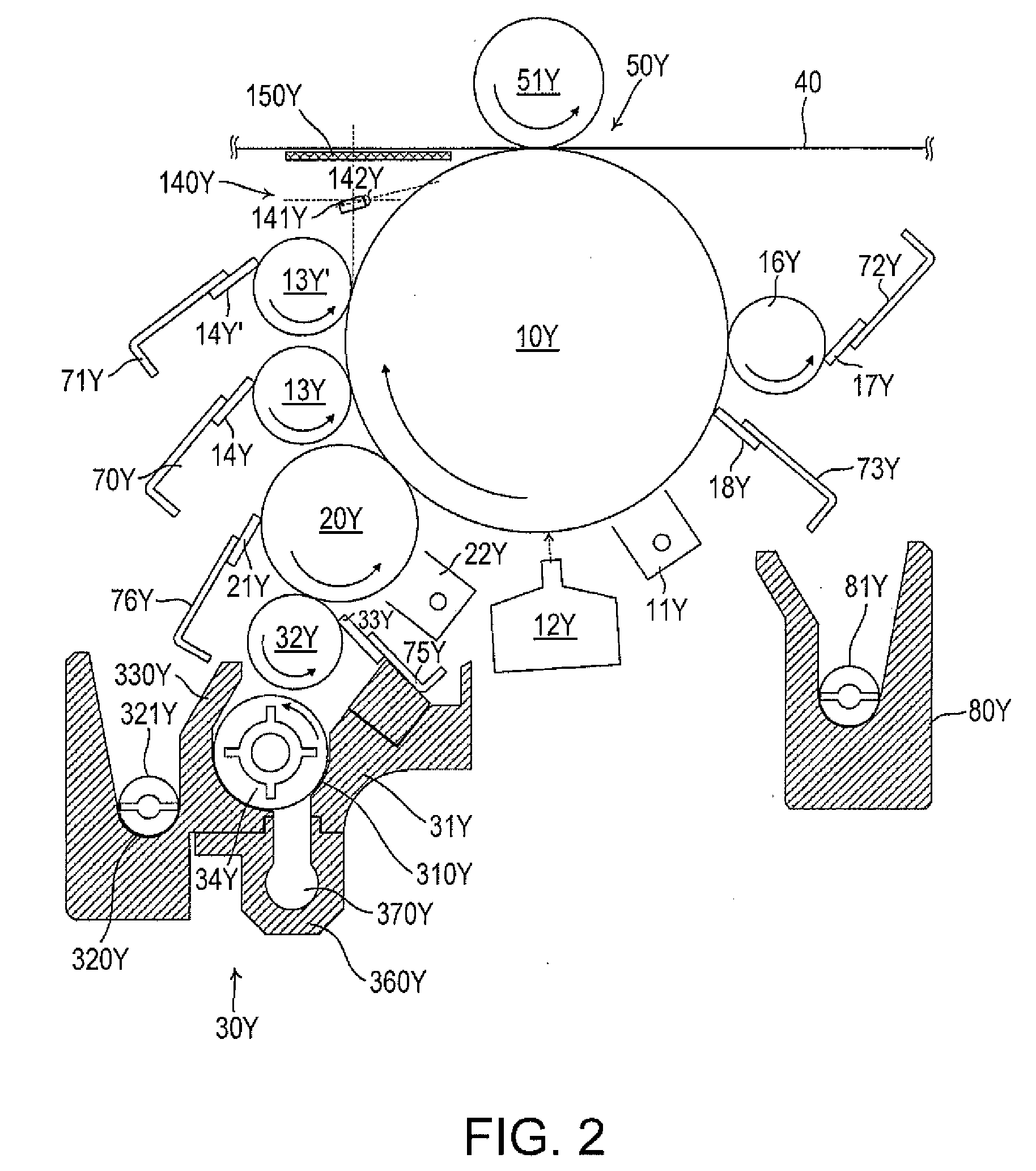
[0039]Exemplary embodiments according to the invention are hereinafter described with reference to the drawings. FIG. 1 illustrates main constituent elements of an image forming apparatus according to an embodiment of the invention. Developing devices 30Y, 30M, 30C, and 30K are positioned in the lower area of the image forming apparatus with respect to image forming areas in respective colors disposed in the central part of the image forming apparatus. An intermediate transfer member 40 and a secondary transfer section (secondary transfer unit) 60 are positioned in the upper part of the image forming apparatus.

[0040]The image forming areas include photoreceptors 10Y, 10M, 10C, and 10K, corona electrifiers 11Y, 11M, 11C, and 11K, not-shown exposure units 12Y, 12M, 12C, and 12K, and other components. Each of the exposure units 12Y, 12M, 12C, and 12K has organic EL element array (or LED array), a driver IC, and a wiring board. The image forming areas uniformly electrify the photorecept...


PUM


Abstract

An image forming apparatus includes: a latent image carrier; an exposure unit which forms a latent image on the latent image carrier; a developing unit which develops the latent image formed on the latent image carrier by the exposure unit using liquid developer; a squeeze roller which contacts the latent image carrier, and applies bias voltage to the latent image carrier after development by the developing unit; an electrification reducing light source which supplies light to the latent image carrier to which bias is applied by the squeeze roller; a transfer member which contacts the latent image carrier and receives the image transferred from the latent image carrier; and a reflection preventing member disposed between the transfer member and the electrification reducing light source.

Description

BACKGROUND[0001]1. Technical Field[0002]The present invention relates to an image forming apparatus which develops a latent image formed on a photoreceptor by liquid developer containing toner and carrier, transfers the image thus developed onto a medium such as recording sheet, and forms the image by fusing and fixing the toner image transferred on the medium. The invention further relates to a photoreceptor unit and a transfer belt unit included in the image forming apparatus.[0003]2. Related Art[0004]Various types of wet-type image forming apparatus have been proposed which develop a latent image by liquid developer having high viscosity and containing toner as solid components dispersed in liquid solvent to visualize an electrostatic latent image. The developer used by this type of wet-type image forming apparatus has solid components (toner particles) suspended in organic solvent (carrier liquid) having high viscosity and electric insulation such as silicon oil, mineral oil, an...

Claims


Application Information

Patent Timeline
Patent Type & Authority Applications(United States)
IPC IPC(8): G03G15/16
CPCG03G15/10G03G21/08G03G15/1605G03G15/11
Inventor TOYAMA, HIROSHIKAMIJO, KOICHIIKUMA, KEN
Owner SEIKO EPSON CORP
Why Eureka
Try Eureka