Liquid Crystal Display Device

a liquid crystal display and display device technology, applied in the direction of lighting and heating apparatus, instruments, optical elements, etc., can solve the problem of increasing the distance from the light entering portion of the light guide plate b>2/b> to the effective light emitting area actually used as a surface light source, so as to reduce the size of the back light and shorten the distance from the point light sour

Active Publication Date: 2008-01-10
PANASONIC LIQUID CRYSTAL DISPLAY CO LTD +1
View PDF2 Cites 5 Cited by
  • Summary
  • Abstract
  • Description
  • Claims
  • Application Information

AI Technical Summary

Benefits of technology

[0033] The effect obtained by the representative inventions as disclosed in this application is briefly described as follows.
[0034] With the liquid crystal display of the invention, the distance from the point light source to the effective light emitting area can be shortened to reduce the size of the back light.

Problems solved by technology

Therefore, there was a problem that the distance from a light entering portion of the light guide plate 2 to the effective light emitting area actually used as a surface light source had to be increased.

Method used


Image

  • Liquid Crystal Display Device
  • Liquid Crystal Display Device
  • Liquid Crystal Display Device

Examples


embodiment 1

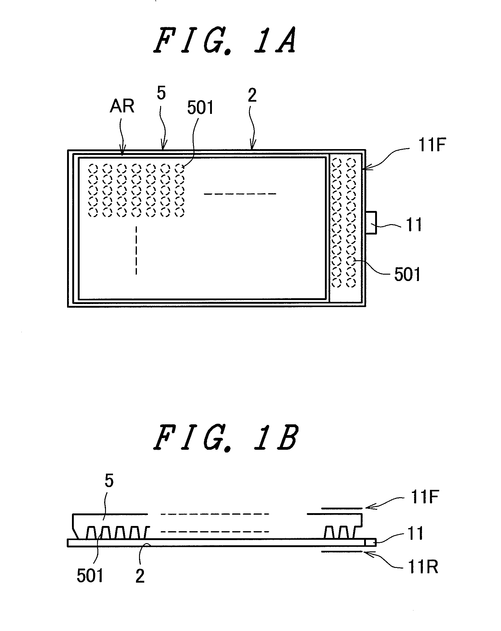
[0052]FIG. 1 is a view showing the schematic constitution of a back light for use in a liquid crystal display according to an embodiment 1 of the invention, wherein FIG. 1A is a schematic plan view and FIG. 1B is a side view.

[0053] The back light of this embodiment has a white light emitting diode 11 (a point light source of the invention) disposed on a side face of a light guide plate 2 and an outgoing light control board 5 disposed on a surface of the light guide plate 2 on the side of the liquid crystal display panel.

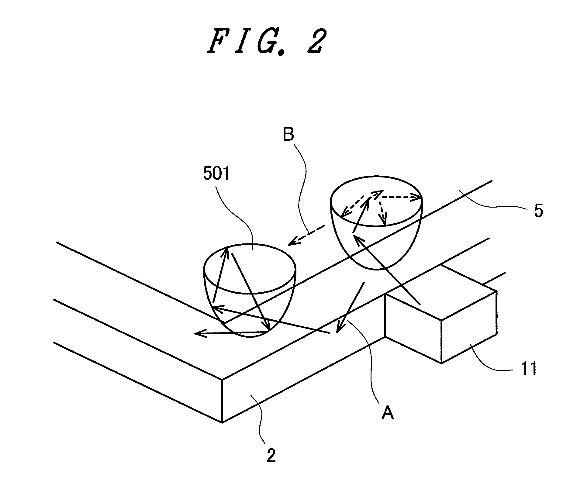
[0054] The outgoing light control board 5 has a plurality of convex portions 501, in which each convex portion 501 is columnar and at least partly circular in cross-sectional shape. And the outgoing light control board 5 is disposed on the light guide plate 2 with the convex portions 501 made adherent to the light guide plate 2.

[0055] Also, the liquid crystal display panel is disposed on the outgoing light control board 5, though not shown in FIG. 1.

[0056] In thi...

embodiment 2

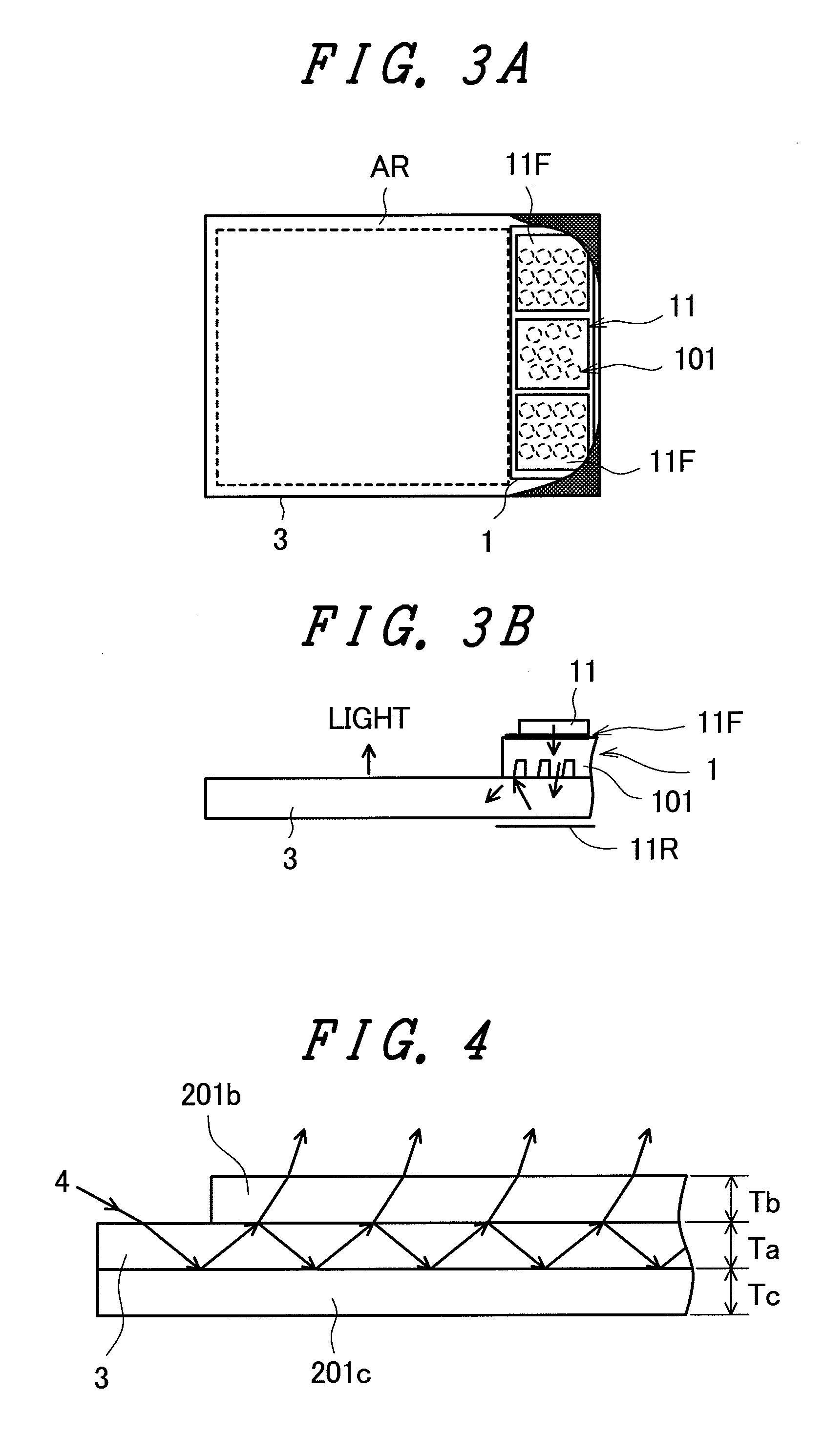
[0065]FIG. 3 is a view showing the schematic constitution of a back light for use in a liquid crystal display according to an embodiment 2 of the invention, wherein FIG. 3A is a schematic plan view and FIG. 3B is a side view.

[0066] The back light of this embodiment has a light guide member 3, an incident light adjustment member (incident light adjustment member of this embodiment) 1 disposed on the light guide member 3, and a white light emitting diode 11 (a point light source of the invention) disposed on the incident light adjustment member 1.

[0067] The incident light adjustment member 1 has a plurality of convex portions 101, in which each convex portion 101 is columnar and at least partly circular in cross-sectional shape. And the incident light adjustment member 1 is disposed on the light guide member 3 with the convex portions 101 made adherent to the light guide member 3.

[0068] A liquid crystal display panel, though not shown in FIG. 3, is disposed on the surface of the li...

embodiment 3

[0097]FIG. 9 is a view showing the schematic constitution of a back light for use in a liquid crystal display according to an embodiment 3 of the invention, wherein FIG. 9A is a schematic plan view and FIG. 9B is a side view.

[0098] The back light of this embodiment employs an incident light adjustment member / outgoing light control board 15 in which the outgoing light control board 5 and the incident light adjustment member 1 are integrated.

[0099] In the back light of this embodiment, a surface light source having highly uniform luminance can be realized even if the distance from the white light emitting diode 11 to the effective light emitting area (AR) is shortened. Further, since the outgoing light control board 5 and the incident light adjustment member 1 are integrated, the high efficiency is attained and the assembling capability is improved.

[0100]FIG. 10 is a view showing the schematic constitution of the liquid crystal display module applying the back light as shown in FIG...


PUM

PropertyMeasurementUnit
thicknessaaaaaaaaaa
thickness Tbaaaaaaaaaa
refractive indexaaaaaaaaaa

Abstract

To shorten the distance from a point light source to an effective light emitting area and reduce the size of a back light. A liquid crystal display having a liquid crystal display panel and a back light disposed on the back face of the liquid crystal display panel, where in the back light has a light guide plate, a point light source disposed on a side face of the light guide plate, and an outgoing light control board disposed on the light guide plate on the side of the liquid crystal display panel, wherein the outgoing light control board has a plurality of convex portions at least partly circular in cross-sectional shape on the surface of the light guide plate, and is disposed on the surface of the light guide plate on the side of the liquid crystal display panel with the convex portions made adherent to the surface of the light guide plate on the side of the liquid crystal display panel, and wherein the convex portions of the outgoing light control board are also formed in an area corresponding to a non-effective area of the back light.

Description

CROSS-REFERENCE TO RELATED APPLICATIONS [0001] The disclosure of Japanese Patent Application No. 2006-155828 filed on Jun. 5, 2006 including the specification, drawings and abstract is incorporated herein by reference in its entirety. BACKGROUND [0002] 1. Field of the Invention [0003] The present invention relates to a liquid crystal display, and more particularly to a technique effectively applied to a back light using a point light source such as a white color light emitting diode (LED: Light Emitting Diode). [0004] 2. Description of the Related Arts [0005] Conventionally, in a liquid crystal display module, a back light (light source) is disposed in the rear (on the back face) of a liquid crystal display panel, whereby an image is displayed by applying a light from the light source to the liquid crystal display panel. [0006] In the liquid crystal display module for use in a portable telephone or the like, a point light source such as a white light emitting diode (LED: Light Emitt...

Claims


Application Information

Patent Timeline
Patent Type & Authority Applications(United States)
IPC IPC(8): G02F1/13357
CPCG02B6/0025G02F1/13452G02B6/0055G02B6/0053
Inventor KURIHARA, HIROSHI
Owner PANASONIC LIQUID CRYSTAL DISPLAY CO LTD
Why Eureka
Try Eureka