Inductive light source module

a light source module and inductive technology, applied in the field of light source modules, can solve the problems of increasing the complexity of the light source module mechanism, people are plunged into darkness without warning, and cannot conduct any action, and achieve good light-emitting uniformity and sensing accuracy.

Inactive Publication Date: 2015-04-28
CAL COMP ELECTRONICS
View PDF5 Cites 5 Cited by
  • Summary
  • Abstract
  • Description
  • Claims
  • Application Information

AI Technical Summary

Benefits of technology

[0007]One of exemplary embodiment is directed to an inductive light source module, which has good light-emitting uniformity and sensing accuracy.
[0009]According to the above descriptions, In the exemplary embodiment, the bi-incident lens capable of simultaneously scattering the visible lights and converging the infrared is disposed on the transparent portion of the casing, and the visible lights emitted from the visible light sources are scattered to the whole transparent portion through the bi-incident lens, such that the visible lights are uniformly propagated to the external environment through the transparent portion to achieve a uniform light-emitting effect. Moreover, the bi-incident lens further converges the infrared that is incident to internal of the casing from the external environment to the infrared sensing device. Therefore, when someone or warm-blooded animal passes through a sensing range of the inductive light source module, the infrared sensing device senses the infrared emitted by human body or warm-blooded animal, and the control unit accordingly drives the visible light sources to emit visible lights to provide illumination. In this way, the inductive light source module of the disclosure can prevent the visible lights from interfering the infrared sensing device without a mask disposed therebetween, by which not only mechanism complexity of the inductive light source module is decreased, the sensing accuracy of the infrared sensing device is also enhanced. Moreover, the visible lights emitted by the visible light sources are scattered to the whole transparent portion through the bi-incident lens, and the light-emitting uniformity of the inductive light source module is further enhanced.

Problems solved by technology

In general residence and office premises, when a blackout disaster caused by human or natural factors is encountered, such as power off, outage or fire disaster, etc., is occurred, people are plunged into darkness without warning and cannot conduct any action.
However, such infrared inductive switch is liable to be interfered by sunlight or a light source of the light source module itself to cause malfunction.
Therefore, a mask has to be additionally installed in the light source module at a region where the infrared sensing device is located to prevent light source interference, which not only increases mechanism complexity of the light source module, but also leads to dark area of the light source module to cause non-uniform lighting.
Therefore, how to eliminate the aforementioned defects is an important issue of the industry.

Method used


Image

  • Inductive light source module
  • Inductive light source module
  • Inductive light source module

Examples


Embodiment Construction

[0019]The present disclosure will now be described more fully with reference to the accompanying drawings, in which exemplary embodiments of the disclosure are shown. The terms used herein such as “above”, “below”, “front”, “back”, “left” and “right” are for the purpose of describing directions in the figures only and are not intended to be limiting of the disclosure. Moreover, in the following embodiments, the same or similar devices are denoted by the same or similar referential numbers.

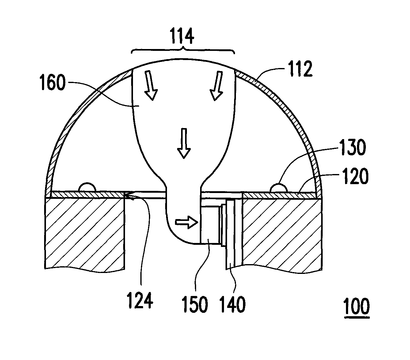
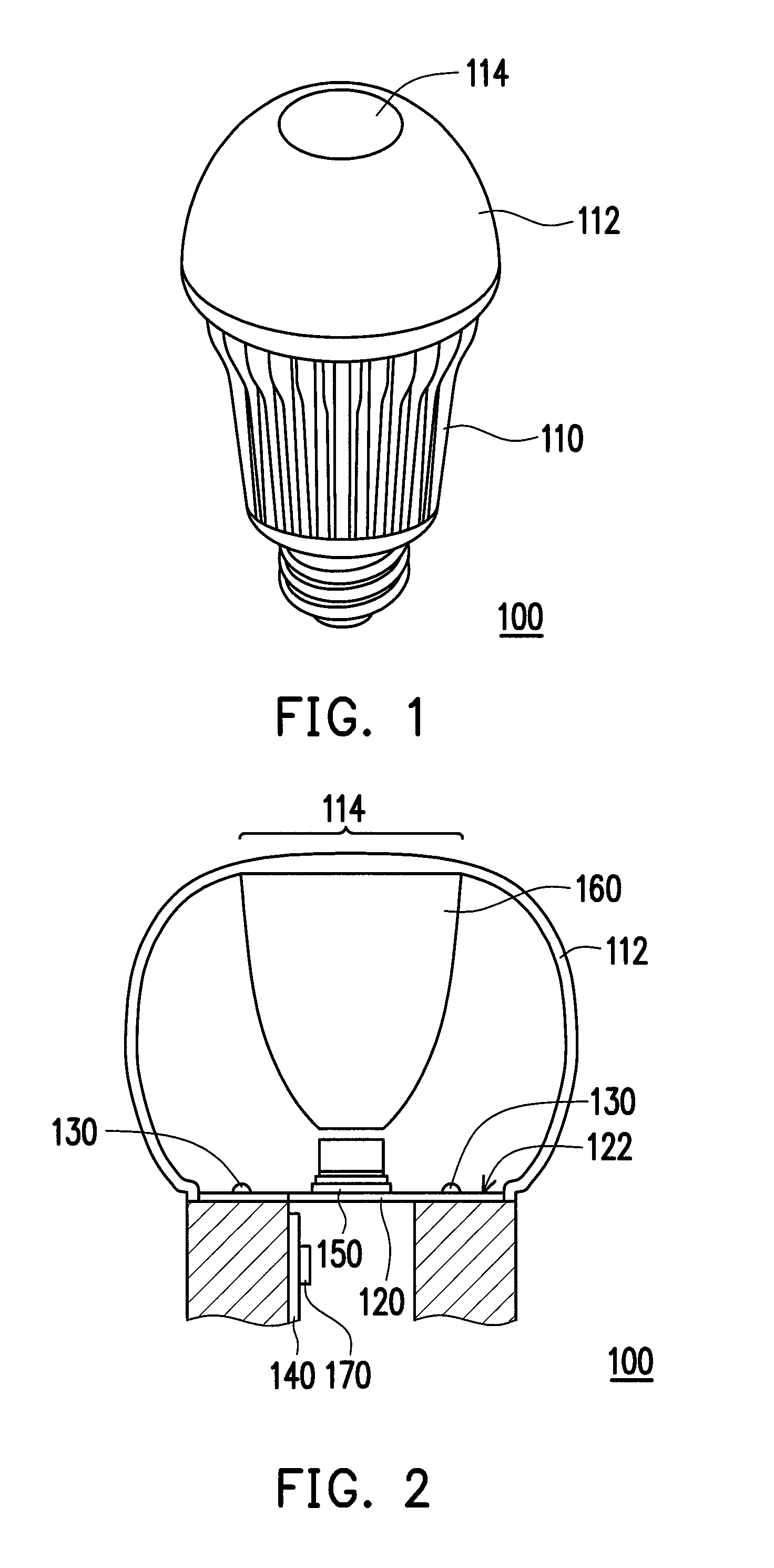
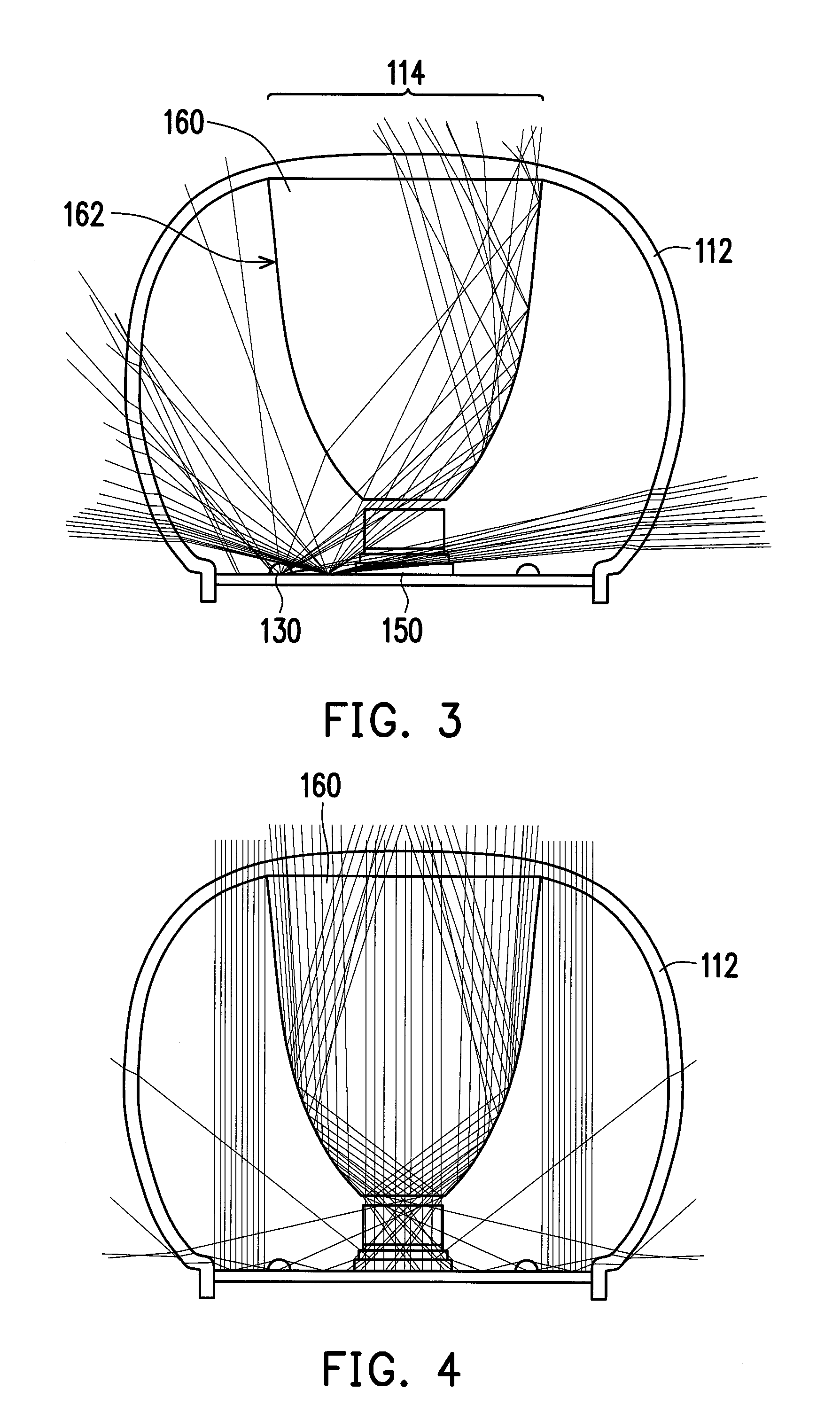
[0020]FIG. 1 is a schematic diagram of an inductive light source module according to an exemplary embodiment. FIG. 2 is a partial cross-sectional view of an inductive light source module according to an exemplary embodiment. Referring to FIG. 1 and FIG. 2, in the present embodiment, the inductive light source module 100 includes a casing 110, a substrate 120, a plurality of visible light sources 130, a circuit board 140, an infrared sensing device 150, a bi-incident lens 160 and a control unit 170....


PUM


Abstract

An inductive light-source module including a casing, a substrate, light sources, a circuit board, an infrared sensing device, a bi-incident lens and a control unit is provided. The substrate disposed in the casing includes a carrying surface facing a transparent portion of the casing. The light sources connected to the substrate are disposed on the carrying surface. The infrared sensing device is connected to the circuit board. The bi-incident lens disposed on the transparent portion is located on a light path of each light for scattering visible lights to pass through the transparent portion and transmit to the outside, and converging the infrared from the outside to the infrared sensing device. The control unit is coupled to the light sources and the infrared sensing device to drive the light sources to emit the visible lights according to a sensing signal generated by the infrared sensing device when sensing the infrared.

Description

CROSS-REFERENCE TO RELATED APPLICATION[0001]This application claims the priority benefit of Taiwan application serial no. 102143028, filed on Nov. 26, 2013. The entirety of the above-mentioned patent application is hereby incorporated by reference herein and made a part of this specification.BACKGROUND[0002]1. Technical Field[0003]The technical field relates to a light source module. Particularly, the technical field relates to an inductive light source module.[0004]2. Related Art[0005]In general residence and office premises, when a blackout disaster caused by human or natural factors is encountered, such as power off, outage or fire disaster, etc., is occurred, people are plunged into darkness without warning and cannot conduct any action. To escape, besides emergency lighting equipment is required, a flashlight has to be provided to facilitate smooth escaping. Moreover, in general residence and office premises, it is also required to guard against burglary, so that security light...

Claims


Application Information

Patent Timeline
Patent Type & Authority Patents(United States)
IPC IPC(8): F21V1/00H05B37/02
CPCH05B37/02F21V19/001F21V23/0471H05B47/13F21V3/02F21V23/045F21K9/232F21Y2115/10Y02B20/40
Inventor HUANG, HSIU-CHILIN, CHIH-FENGWANG, CHUN-MINLIN, YUEH-FENG
Owner CAL COMP ELECTRONICS
Why Eureka
Try Eureka