Optomechanical MEMS device including a proof mass and an illumination mitigating mechanism

a technology of optical microsensors and proof mass, which is applied in the direction of optical radiation measurement, lighting and heating apparatus, instruments, etc., can solve the problems of reducing the dynamic measurement range and affecting the operation of the mems device, and achieve the effect of reducing the amount and/or the effect of stray ligh

Active Publication Date: 2013-11-12
RAFAEL ADVANCED DEFENSE SYSTEMS
View PDF6 Cites 0 Cited by
  • Summary
  • Abstract
  • Description
  • Claims
  • Application Information

AI Technical Summary

Benefits of technology

[0005]The present invention relates to an improved optical MEMS (microelectromechanical system) device wherein the amount and / or effect of stray light (illumination that is mis-directed, reflected light, etc.) is reduced.
[0008]It is an object of the invention to reduce the undesirable effect of noise and parasitic signal resulting from illumination, in MEMS optic sensing devices. Light arriving from the light source is distributed on a photodiode for producing an electrical signal. However, the peripheral electronics devices (e.g. electrostatic discharge diodes, pressure gauges, thermometers and VLSI amplifiers) also can be affected by the illumination, either by direct light or indirect light reflected from various surfaces of the device, for example reflected from electronic circuits of the MEMS device or package, from the illumination system or as a result of scattered light. This undesirable effect imparts a negative influence upon operations of the MEMS device as it adds noise and parasitic signals to the desirable electronic signal and may reduce the dynamic measurement range.

Problems solved by technology

This undesirable effect imparts a negative influence upon operations of the MEMS device as it adds noise and parasitic signals to the desirable electronic signal and may reduce the dynamic measurement range.

Method used


Image

  • Optomechanical MEMS device including a proof mass and an illumination mitigating mechanism
  • Optomechanical MEMS device including a proof mass and an illumination mitigating mechanism
  • Optomechanical MEMS device including a proof mass and an illumination mitigating mechanism

Examples


Embodiment Construction

refers to the accompanying drawings referred to above. Dimensions of components and features shown in the figures are chosen for convenience or clarity of presentation and are not necessarily shown to scale. Wherever possible, the same reference numbers are used throughout the drawings and the following description to refer to the same and like parts.

DETAILED DESCRIPTION OF EMBODIMENTS OF THE PRESENT INVENTION

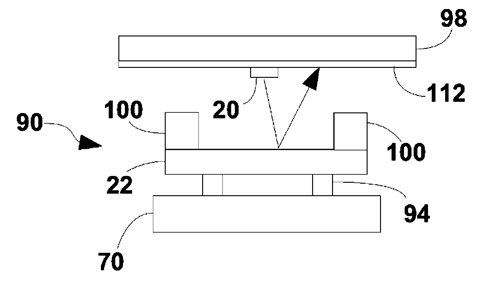
[0023]The present invention relates to designs and configurations for reducing or eliminating stray light in MOEMS and / or reducing or eliminating the effect of direct and indirect (stray) parasitic light on the peripheral electronics of MOEMS. Below, a number of exemplary solutions are described by way of example on a micro-machined optical inertial sensing device. It should be noted that embodiments of the invention can be implemented on a variety of MOEMS devices.

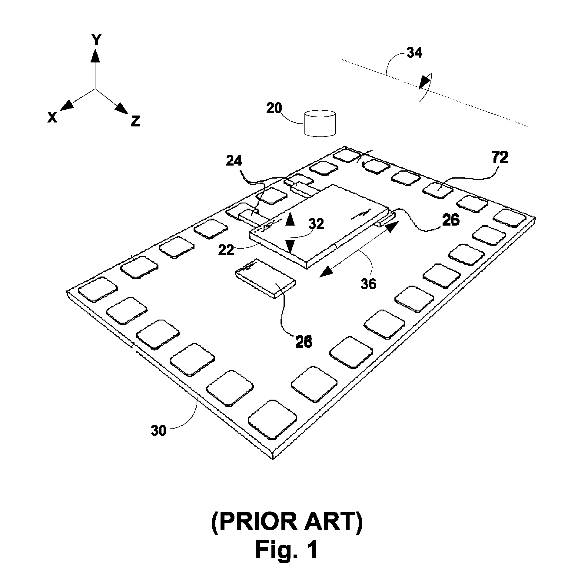
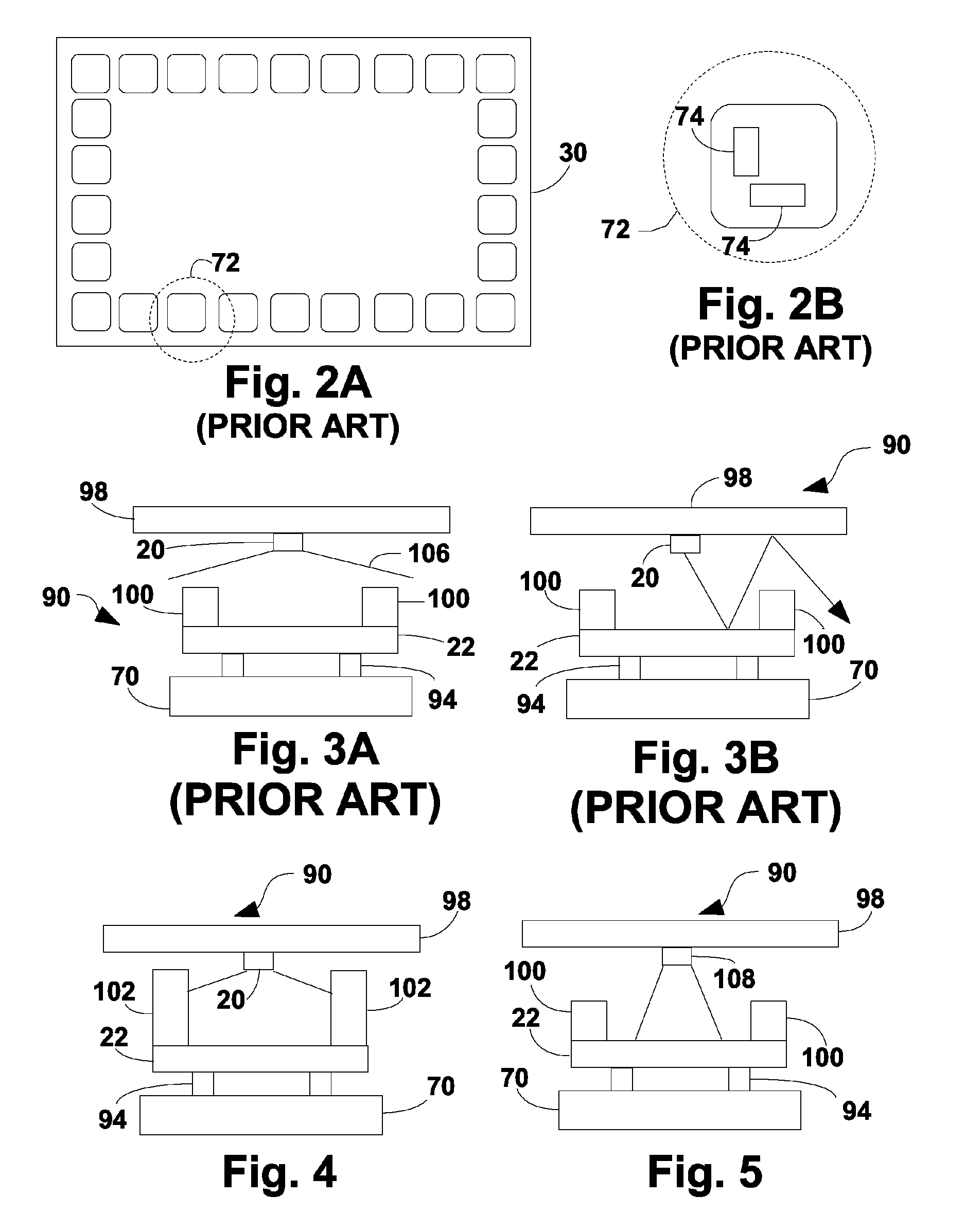
[0024]Referring first to FIG. 1, FIGS. 2A and 2B, and FIGS. 3A and 3B, there is shown a typical (prior art) micro-...


PUM


Abstract

A micro-opto-electro-mechanical system having a proof mass; at least one illumination source for providing illumination; an illumination detector; peripheral electronics; and an illumination mitigating mechanism for mitigating the effect of illumination emitted from the at least one illumination source on the peripheral electronics. According to various embodiments, the illumination mitigating mechanism includes handles disposed on the proof mass, an illumination collimating device, a substrate with a recess, a narrow beam light source, an illumination absorbing layer or optical limiters.

Description

FIELD OF THE INVENTION[0001]The present invention relates to MEMS (microelectromechanical systems) technology, in particular MEMS employing optical microsensors.BACKGROUND OF THE INVENTION[0002]Micro-electro-mechanical systems (MEMS) provide an electrical output in response to movement. MEMS are incorporated in an increasing number of sensor and actuator devices especially in applications making use of orientation, alignment and stabilization such as medical devices, photographical equipment, transportation navigation and inertial sensors, weaponry, and so on. MEMS are produced using several known microprocessing techniques, including: photolithography, wet etching, dry etching, evaporation, chemical-vapor deposition, oxidation, etc. is[0003]Micro-opto-electromechanical systems (MOEMS) are a special class of MEMS which involves sensing or manipulating optical signals using integrated mechanical and electrical systems.[0004]Micro-electromechanical optical inertial sensing devices mak...

Claims


Application Information

Patent Timeline
Patent Type & Authority Patents(United States)
IPC IPC(8): G01J1/32
CPCG01C19/5755G01P15/093
Inventor RONEN, AVIVLAHAV, ORENBEN ITZHAK, SEGEVSHALEV, HAIMKOGUT, LIOR
Owner RAFAEL ADVANCED DEFENSE SYSTEMS
Why Eureka
Try Eureka