Computer mouse capable of restraining rebound force

a computer mouse and rebound force technology, applied in computing, instruments, electric digital data processing, etc., can solve the problems of generating double-click events and buttons that cannot be clicked exactly, and achieve the effect of stably disposed

Active Publication Date: 2018-10-09
DEXIN ELECTRONICS LTD +1
View PDF16 Cites 3 Cited by
  • Summary
  • Abstract
  • Description
  • Claims
  • Application Information

AI Technical Summary

Benefits of technology

[0009]Moreover, the elastic element is received in the accommodating slot on the top board of the main body, so that the elastic element can be stably disposed on the top board of the main body.

Problems solved by technology

However, after a button of the computer mouse is pressed, a rebound force is produced on the button because the button has a longer arm of force, so that the button cannot be clicked exactly and would generate a double-click event.

Method used


Image

  • Computer mouse capable of restraining rebound force
  • Computer mouse capable of restraining rebound force
  • Computer mouse capable of restraining rebound force

Examples


first embodiment

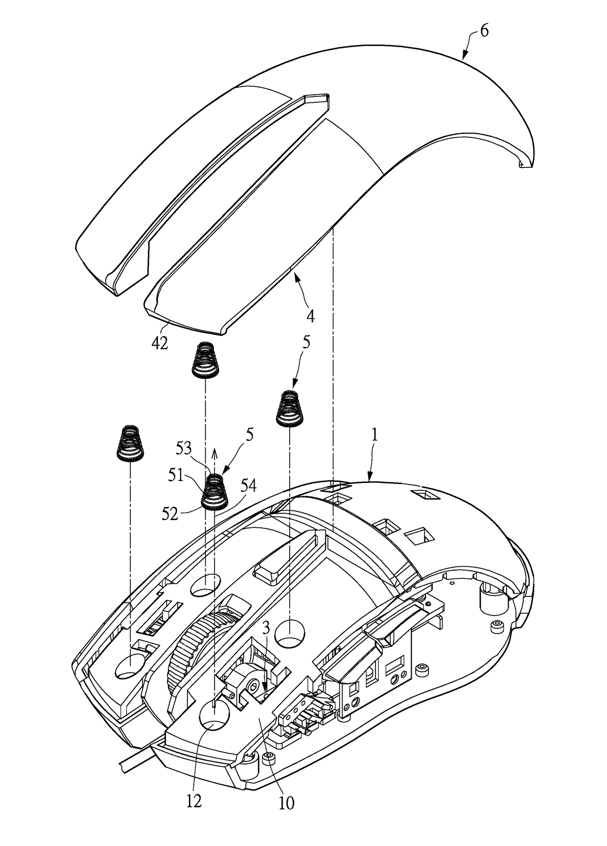
[0021]Reference is made to FIG. 1 to FIG. 4. The present disclosure provides a computer mouse having a button and being capable of restraining rebound force, which includes a main body 1, a circuit board 2, a switch module 3, a button 4 and an elastic element 5.

[0022]The main body 1 has a top board 10, and the top board 10 is disposed on a top of the main body 1. The main body 1 is disposed with a receiving space 11 therein. The circuit board 2 and the switch module 3 are installed in the receiving space 11. The switch module 3 is disposed on the circuit board 2. The switch module 3 is electrically connected to the circuit board 2. The receiving space 11 is an inner space of the main body 1, which is equipped with necessary elements such as an optical reading module and a roller and so on for operating a computer mouse. These elements are not described here.

[0023]The button 4 is a long-shaped board and is movably disposed on the top board 10 of the main body 1 in an up-and-down mann...

second embodiment

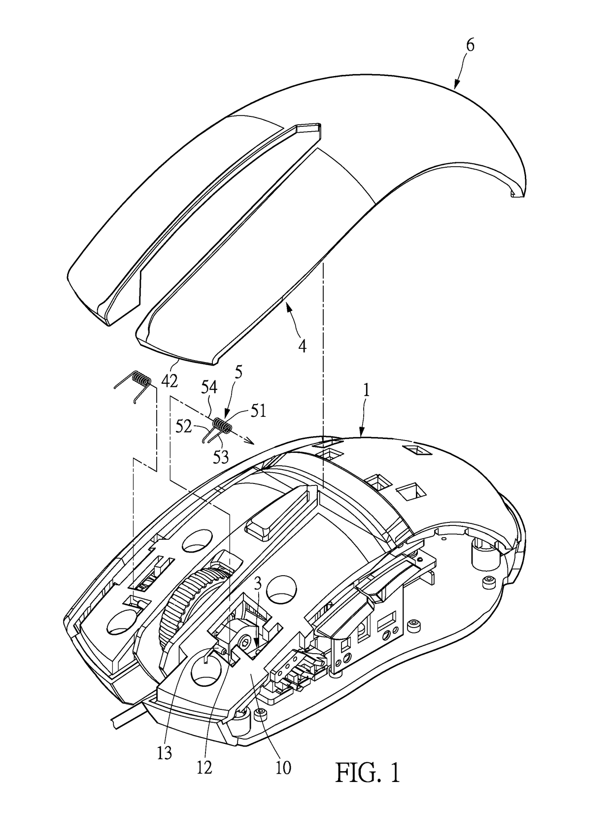
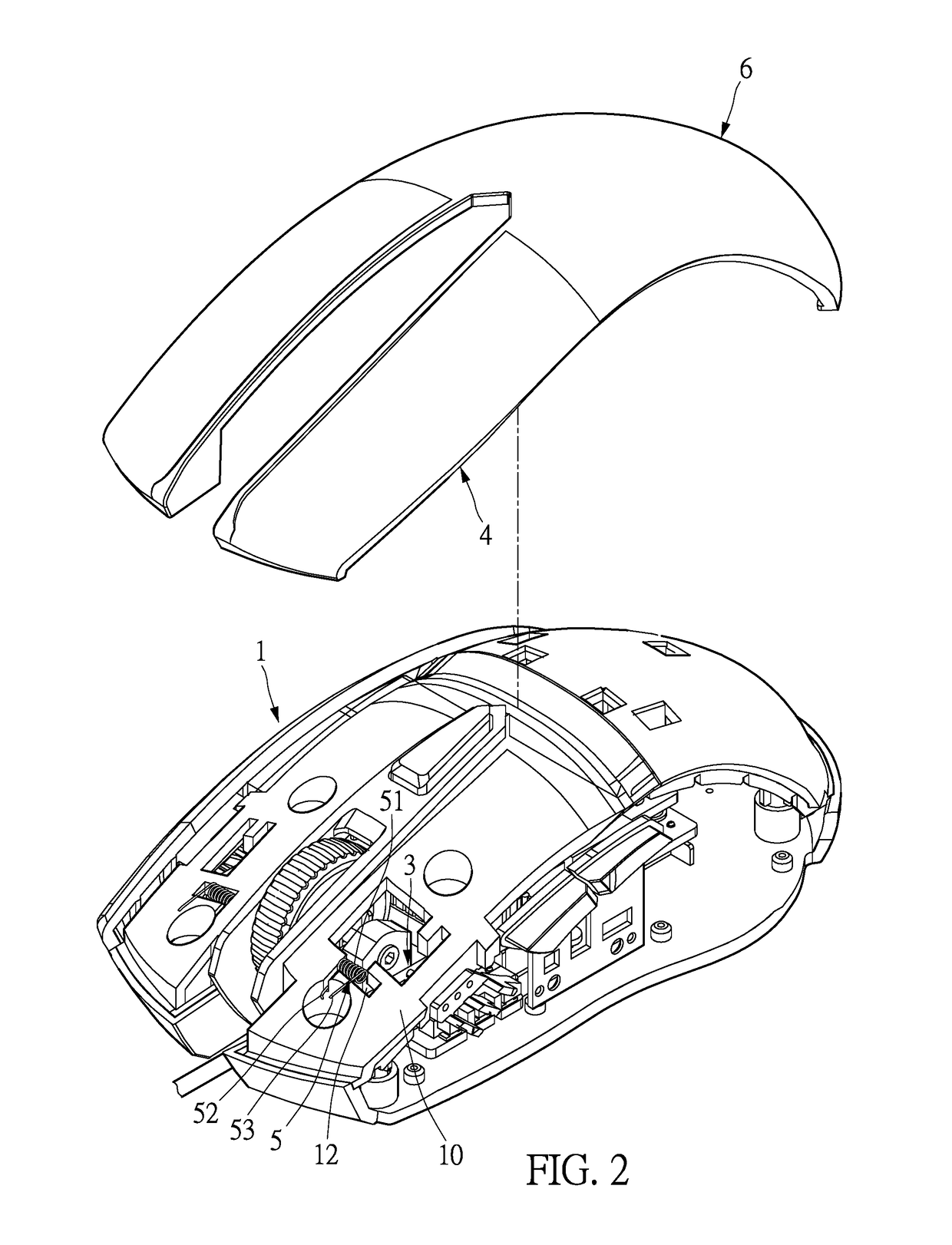
[0031]Reference is made to FIG. 5 to FIG. 8. The main difference between this embodiment and the above embodiment is that, the elastic elements 5 of this embodiment are compression springs. Each elastic element 5 has a main part 51 which can be a spiral structure. The elastic element 5 has a first end 52 and a second end 53. The first end 52 and the second end 53 are respectively formed at two ends of the main part 51. The first end 52 and the second end 53 are ring-shaped. A diameter of the first end 52 is larger than that of the second end 53, so that the main part 51 is a tapered screw. Each button 4 can be equipped with two elastic elements 5, and the two elastic elements 5 are respectively disposed at a front position of the switch module 3 and a rear position of the switch module 3. The elastic element 5 is disposed between the top board 10 of the main body 1 and the button 4. At least one elastic element 5 is close to the free end 42 of the button 4, and the elastic element 5...

third embodiment

[0033]Reference is made to FIG. 9. The main difference between this embodiment and the above embodiment is that, the elastic elements 5 of this embodiment are blade springs. Each elastic element 5 has a main part 51, and the main part 51 can be in a blade shape. The elastic element 5 has a first end 52 and a second end 53. The first end 52 and the second end 53 are formed on the main part 51. Each button 4 is correspondingly equipped with an elastic element 5. The elastic element 5 is close to the free end 42 of the button 4. The elastic element 5 is disposed between the top board 10 of the main body 1 and the button 4. The elastic element 5 contacts the inner side of the button 4, so as to provide the button 4 with a recovery force of moving upwards.

[0034]In this embodiment, the elastic elements 5 are respectively received in the accommodating slots 12 which are formed on the top board 10 of the main body 1. The accommodating slot 12 can be square recess. The first end 52 of the el...


PUM


Abstract

A computer mouse capable of restraining rebound force includes a main body, a circuit board, a switch module, a button and an elastic element. The circuit board and the switch module are assembled in a receiving space of the main body. The button is movably disposed on a top board of the main body in an up-and-down manner. The elastic element is disposed between the top board and the button and close to a free end of the button. The elastic element has a first end which is abutted against the top board of main body and a second end which is abutted against an inner side of the button. Thus, the elastic element can restrain the rebound force when the button is pressed, and the button can be clicked exactly without generating a double-click event.

Description

BACKGROUND OF THE INVENTION1. Field of the Invention[0001]The present invention is related to a computer mouse having a button. In particular, the present disclosure relates to a computer mouse having a button and being capable of restraining rebound force.2. Description of Related Art[0002]Keyboards and computer mice are the most commonly-used input devices for computers. A conventional computer mouse usually has a left button, a right button, and a scroll wheel between the left and right buttons. The buttons are movably disposed on a main body of the computer mouse in an up-and-down manner. A triggering portion is disposed on an inner side of the button and arranged above a micro-switch. When the button is pressed, the micro-switch can be activated by the triggering portion.[0003]With the increasing popularity of video games, game fans share experiences and exchange game tips through livestreams, which draws public attention. Players who possess superb gameplay mechanics or strate...

Claims


Application Information

Patent Timeline
Patent Type & Authority Patents(United States)
IPC IPC(8): G06F3/0354
CPCG06F3/03543
Inventor LU, HO-LUNGLAI, YEN-YAO
Owner DEXIN ELECTRONICS LTD
Why Eureka
Try Eureka