Antenna structure and image display device including the same

a technology of image display device and antenna structure, which is applied in the direction of individually energised antenna array, resonant antenna, instruments, etc., can solve the problem of not sufficiently considering the antenna construction, and achieve the effects of enhancing flexibility and mechanical durability, preventing excessive absorption of signal radiated from the antenna unit by ground layer and/or conductive member of the display panel, and high reliability

Pending Publication Date: 2022-06-23
DONGWOO FINE CHEM CO LTD
View PDF5 Cites 0 Cited by
  • Summary
  • Abstract
  • Description
  • Claims
  • Application Information

AI Technical Summary

Benefits of technology

[0027]Accordingly, a total thickness of the image display device including the antenna structure may not be increased, and a neutral plane for a smooth folding of the image display device may be maintained. Thus, flexible properties and mechanical durability may be enhanced while maintaining the antenna radiation performance, so that the image display device having high reliability including an antenna may be implemented.
[0028]A first adhesive layer may be disposed between the antenna structure and a display panel of the image display device. A thickness of the first adhesive layer may be within a predetermined range. Accordingly, excessive absorption of a signal radiated from the antenna unit by a ground layer and / or a conductive member of the display panel may be prevented, and a circuit board may be stably disposed.
[0029]In some embodiments, a ground layer may be disposed under a display panel included in the image display device. In this case, the conductive member and the ground layer of the display panel may be provided together as a ground of the antenna unit. Accordingly, a vertical radiation property of the antenna unit may be implemented with high efficiency and high reliability.

Problems solved by technology

For example, Korean Published Patent Application No. 2013-0113222 discloses an antenna integrated into a mobile terminal, but does not sufficiently consider the antenna construction as described above.

Method used


Image

  • Antenna structure and image display device including the same
  • Antenna structure and image display device including the same
  • Antenna structure and image display device including the same

Examples


Embodiment Construction

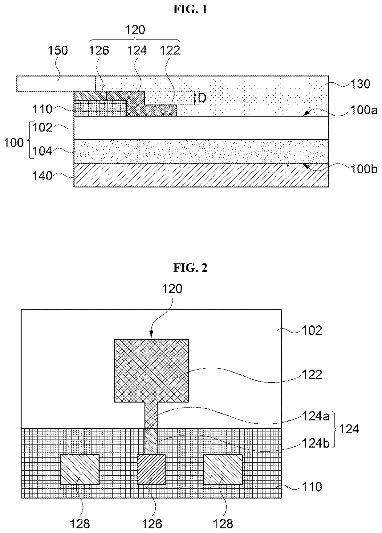
[0034]According to exemplary embodiments of the present invention, there is provided an antenna structure including a light-shielding pattern and an antenna unit.

[0035]The antenna structure may include, e.g., a microstrip patch antenna fabricated in the form of a transparent film. , a monopole antenna or a dipole antenna. The antenna structure may be applied to communication devices for a mobile communication of a high or ultrahigh frequency band corresponding to a mobile communication of, e.g., 3G, 4G, 5G or higher.

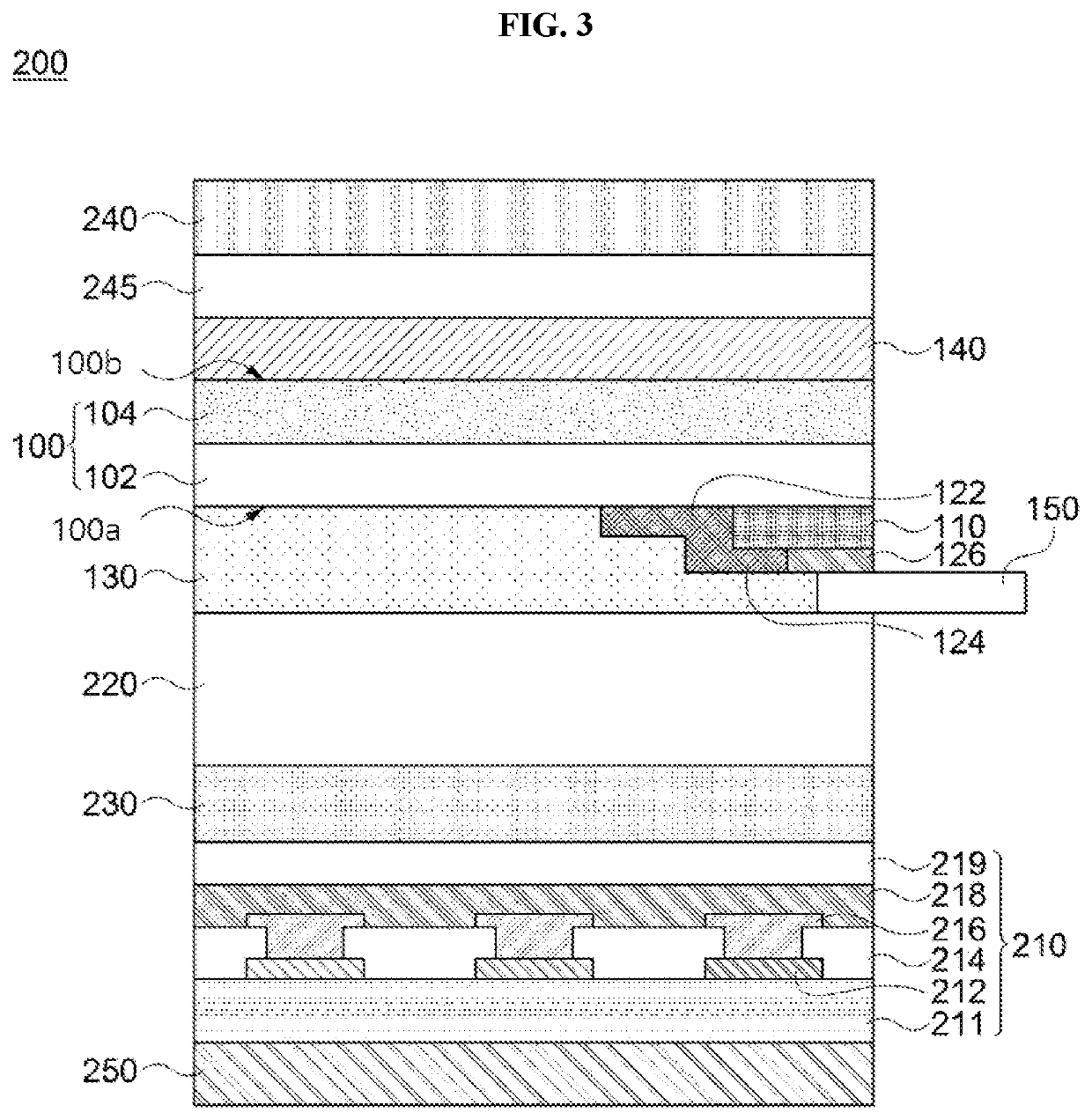
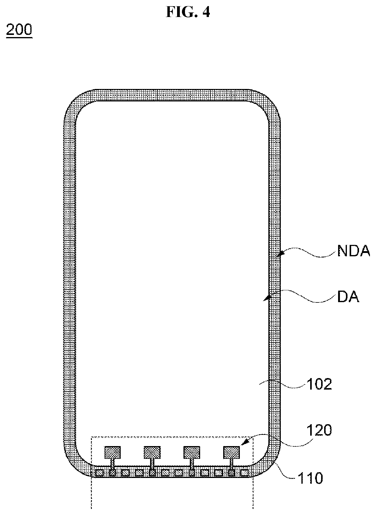
[0036]According to exemplary embodiments of the present invention, there is also provided an image display device including the antenna structure. An application of the antenna structure is not limited to the image display device, and the antenna structure may be applied to various objects or structures such as a vehicle, a home electronic appliance, an architecture, etc.

[0037]Hereinafter, the present invention will be described in detail with reference to the accompanyi...


PUM

PropertyMeasurementUnit
thicknessaaaaaaaaaa
thicknessaaaaaaaaaa
dielectric constantaaaaaaaaaa

Abstract

An antenna structure according to an embodiment of the present disclosure includes a support layer having a first surface and a second surface facing each other, a light-shielding pattern disposed on a peripheral portion of the first surface of the support layer, a radiator disposed at the same level as that of the light-shielding pattern on the first surface of the support layer, and a signal pad disposed on the light-shielding pattern and electrically connected to the radiator. A spatial efficiency of the antenna structure may be improved and a thickness of the image display device may be reduced to enhance a bending property.

Description

CROSS-REFERENCE TO RELATED APPLICATION AND CLAIM OF PRIORITY[0001]This application claims priority to Korean Patent Application No. 10-2020-0177293 filed on Dec. 17, 2020 in the Korean Intellectual Property Office (KIPO), the entire disclosures of which are incorporated by reference herein.BACKGROUND1. Field[0002]The present invention relates to an antenna structure and an image display device including the same. More particularly, the present invention relates to an antenna structure including an antenna unit and a light-shielding pattern, and an image display device including the same.2. Description of the Related Art[0003]As information technologies have been developed, a wireless communication technology such as Wi-Fi, Bluetooth, etc., is combined with an image display device in, e.g., a smartphone form. In this case, an antenna may be combined with the image display device to provide a communication function.[0004]Recently, as a bendable image display device such as flexible di...

Claims


Application Information

Patent Timeline
Patent Type & Authority Applications(United States)
IPC IPC(8): G02F1/1335H01Q1/24
CPCG02F1/133512H01Q1/243H01Q1/38H01Q1/12H01Q1/22H01Q1/48H01Q21/08H01Q9/045
Inventor HUH, YOON HOLEE, YOUNG SULEE, JAE HYUN
Owner DONGWOO FINE CHEM CO LTD
Why Eureka
Try Eureka