
Fuel injector

a fuel injector and fuel technology, applied in mechanical equipment, machines/engines, electric control, etc., can solve the problems of reducing the maximum diameter and reducing the service life of the nozzle body. , to achieve the effect of improving service life, reducing cost and optimising performan

Active Publication Date: 2018-10-16
WESTPORT FUEL SYST CANADA INC
View PDF37 Cites 0 Cited by
  • Summary
  • Abstract
  • Description
  • Claims
  • Application Information

AI Technical Summary

Benefits of technology

[0012]Advantageously, because the nozzle body assembly is formed from two parts, the different materials can be selected to improve manufacturability, reduce cost and optimise performance. Preferably, therefore, the tip part and the needle guide part are made from different materials. For example, the tip part may be made from a high-grade steel with good wear resistance and very good machinability. The needle guide part may be made from a lower-grade steel. Alternatively, or in addition, the tip part and the needle guide part may be made from materials that have been subjected to different heat treatments.
[0013]The design of the nozzle tip of an injector is typically tailored to suit a particular application. In particular, the number, position, angle and shape of the fuel outlet orifices in the nozzle tip can be selected to optimise performance of the injector for a particular combustion chamber design. In the present invention, only the tip part of the nozzle body assembly needs be designed to suit a particular application. The needle guide part of the nozzle body assembly, and the remaining components of the injector, can be of a common design across multiple applications. Therefore the present invention provides an injector design that can be readily tailored for different applications at minimum cost.
[0015]The injector may comprise a cap nut arranged to clamp the tip part to the needle guide part. In one embodiment, the tip part comprises a shoulder, and the cap nut is arranged to engage with the shoulder to clamp the tip part to the needle guide part. Preferably, the shoulder is disposed at an end of the tip part, opposite the seating region. In this way, the needle guide part need not include a shoulder for engagement with the cap nut, so that the diameter of the cap nut can be maximised along the length of the cap nut, creating more space within the cap nut for fuel passages and the like.

Problems solved by technology

The restricted maximum diameter of the nozzle body can be particularly limiting in the design of dual fuel injectors.
Tool steel is relatively expensive and difficult to machine, which makes the component cost of the nozzle body relatively high.

Method used


Image

  • Fuel injector
  • Fuel injector
  • Fuel injector

Examples


first embodiment

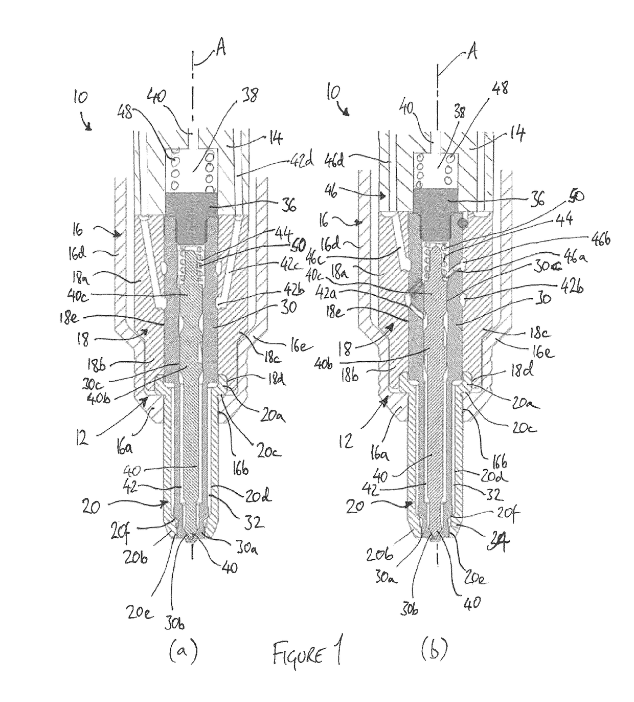
[0028]FIGS. 1(a) and 1(b) show a nozzle region of a fuel injector 10 according to the present invention. The injector 10 is elongate to define an injector axis A. FIG. 1(a) is a sectional view taken on a first plane that contains the injector axis A, and FIG. 1(b) is a sectional view taken on a second plane that also contains the injector axis A and is perpendicular to the first plane.

[0029]The injector 10 comprises a nozzle body assembly 12, an injector body 14, and a cap nut 16. Only the lower ends of the injector body 14 and the cap nut 16 are illustrated in FIGS. 1(a) and 1(b).

[0030]The nozzle body assembly 12 comprises a needle guide part 18 and a tip part 20. The needle guide part 18 comprises an upper, relatively large diameter cylindrical region 18a and a lower, smaller-diameter cylindrical region 18b. The upper and lower regions 18a, 18b are separated by a frustoconical region 18c. The tip part 20 is generally tubular, and comprises an upper end region 20a and a tip region ...

second embodiment

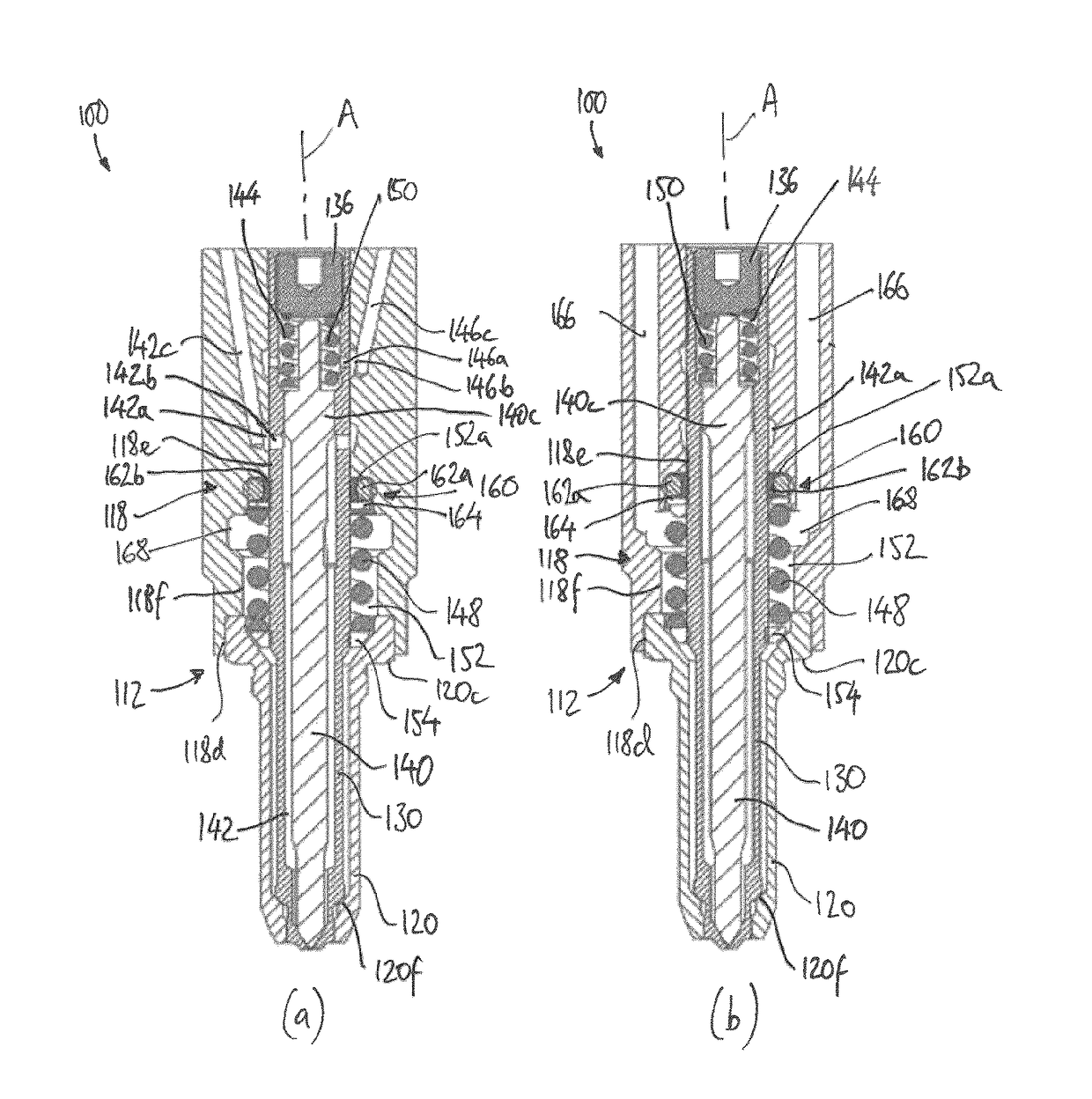
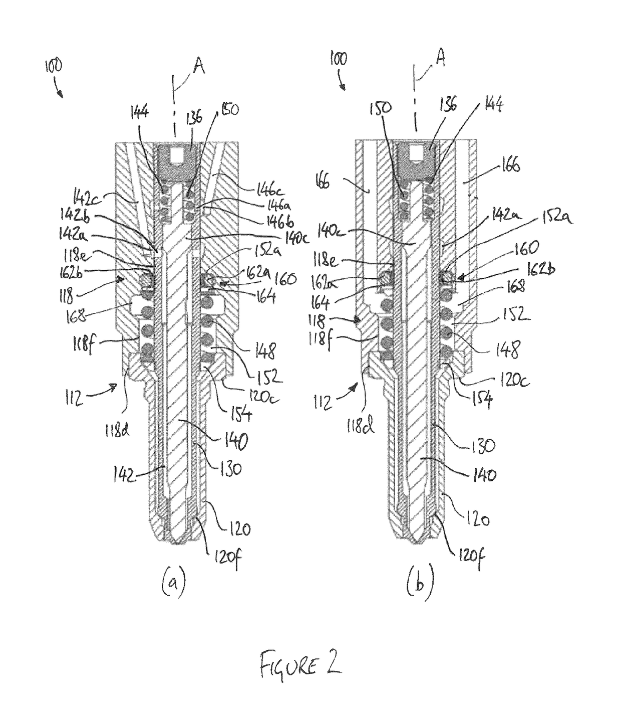
[0049]In this second embodiment, the first biasing spring 148 for the outer valve needle 130 is housed within the nozzle body assembly 112, instead of in the injector body. To accommodate the first biasing spring 148, the needle guide part 118 of the nozzle body assembly 112 includes a spring cavity 152 that is defined by an enlarged diameter lower bore region 118f that connects at its uppermost end with the guide bore 118e and at its lowermost end with the recess 118d.

[0050]A lower end of the first biasing spring 148 seats upon a collar 154 that is press-fitted or otherwise attached to the outer surface of the outer valve needle 130. In this way, the first biasing spring 148 acts through the collar 154 to bias the outer valve needle 130 into engagement with the seating region 120f of the tip part 120. An upper end of the first biasing spring 148 serves to retain a sealing assembly 160 in position against a surface defined by the uppermost end 152a of the spring cavity 152.

[0051]Th...


PUM


Abstract

A fuel injector (100) for an internal combustion engine is disclosed. The fuel injector is particularly suitable for use as a dual fuel injector, and comprises a generally tubular outer valve needle (130), an inner valve needle (140) slidably received in the outer valve needle (130), and a nozzle body assembly (112) comprising a tip part (120) and a needle guide part (118). The tip part (120) defines a seating region (120f) for the outer valve needle (130), and the needle guide part (118) comprises a guide bore (118e) for slidably receiving the outer valve needle (130). In one embodiment, the tip part (120) and the needle guide part (118) are made from different materials, and a biasing spring (148) for the outer valve needle (130) is housed in the nozzle body assembly (112).

Description

FIELD OF THE INVENTION[0001]The present invention relates to a fuel injector suitable for controlling the delivery of two different fuels into an internal combustion engine. In particular, but not exclusively, the invention relates to a fuel injector suitable for injecting a gaseous fuel and a liquid fuel.BACKGROUND TO THE INVENTION[0002]Internal combustion engines for heavy-duty and industrial applications are typically fuelled by diesel. However, the use of natural gas as an alternative to diesel is of increasing interest. Natural gas is relatively abundant and relatively cheap, and can, in principle, provide similar levels of power to diesel whilst producing lower particulate and nitrogen oxide (NOx) emissions.[0003]Natural gas can be used in place of diesel to fuel a compression-ignition engine, in which combustion of the fuel occurs as a result of compression of the air-fuel mixture in the cylinder. However, because natural gas has a higher auto-ignition temperature than diesel...

Claims


Application Information

Patent Timeline
Patent Type & Authority Patents(United States)
IPC IPC(8): F02M61/12F02M43/04F02M47/02F02M63/00F02M51/06F02D41/00F02D19/06
CPCF02M61/12F02M47/025F02M51/0653F02M51/0675F02M63/001F02M43/04Y02T10/36F02D19/0694F02D41/0025F02D41/0027F02M2200/16F02M2200/46F02M2200/50F02M2200/90F02M2547/006Y02T10/30
Inventor MEEK, GEORGE A.PANESAR, LUKHBIR
Owner WESTPORT FUEL SYST CANADA INC
Learn More