
Inner tube protective device

a protective device and inner tube technology, applied in the direction of wheels, tire beads, vehicle components, etc., can solve the problems of small holes, tools used to remove or install inner tubes, and punctured inner tubes, etc., to reduce the occurrence of pinch flats, efficient and less costly

Active Publication Date: 2018-10-23
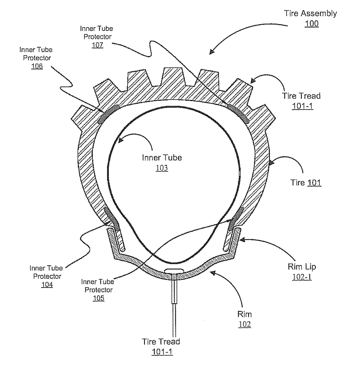
RJ ENG ENTERPRISES
View PDF8 Cites 0 Cited by
  • Summary
  • Abstract
  • Description
  • Claims
  • Application Information

AI Technical Summary

Benefits of technology

[0004]Accordingly, a need exists for a solution that significantly minimizes the occurrence of pinch flats within inner tubes in an efficient and less costly manner. Embodiments of the present invention provide a novel solution for preventing pinch flats or “snake bites” as well as installation flats (e.g., flats caused by installation tools) incurred by an inner tube as a result of the wheel striking an object. Embodiments of the present invention are directed to an inner tube protector that fits within a tire and provides mechanical protection to the inner tube against tire strikes. Embodiments of the present invention include an inner region adapted to support an inner tube installed around a rim of a spoked wheel. Additionally, embodiments of the present invention include an outer region adapted for insertion within and against the rim lip of the rim which extends radially outward to provide protection to the inner tube responsive to the wheel striking an object. As such, embodiments of the present invention may be positioned between the rim and inner tube in a manner that dulls an edge of the rim lip and, thereby, provides protection to the inner tube when compressed against the otherwise sharp edges of the rim lip. Furthermore, embodiments of the present invention can be enclosed within an installed tire on the spoked wheel.
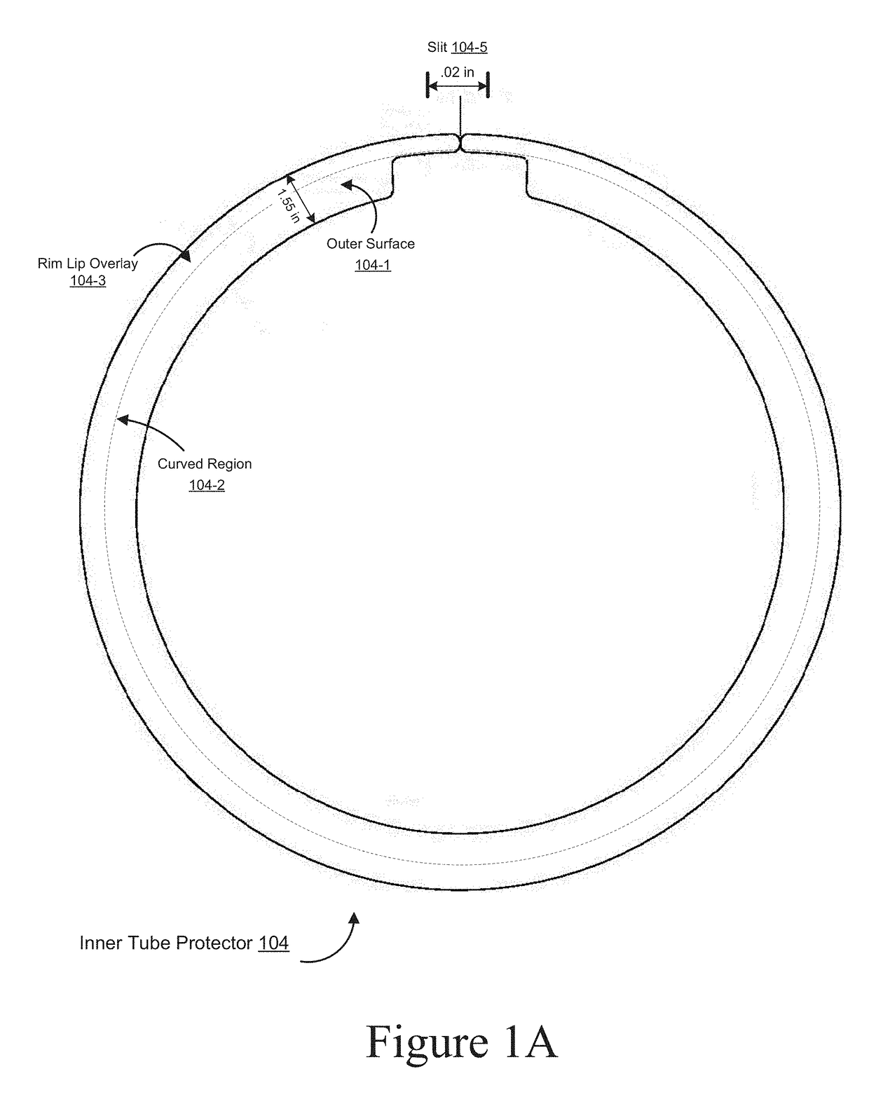
[0005]More specifically, embodiments of the present invention are implemented as an inner tube protector. The inner tube protector includes a generally circular flat member that includes an inner region adapted to support an inner tube installed around a rim of a bicycle wheel. Also, the generally circular flat member includes an outer region adapted for insertion within and against a rim lip of the rim, in which the outer region is adapted to extend radially outward to provide protection to the inner tube responsive to the wheel striking an object, the outer region is adapted to be positioned between the rim and the inner tube to dull an otherwise sharp edge of the rim lip and further adapted to be enclosed within an installed tire on the wheel.
[0008]In one embodiment, the present invention is implemented as a rim for protecting an inner tube. The rim includes a channel region circumferentially located along an exterior portion of the rim, in which the channel region is adapted for mounting a spoked wheel. The rim also includes a generally circular flat member integrated into an outer periphery of a rim lip of the rim in which the flat member includes an inner region adapted to support an inner tube installed within the channel region and an outer region adapted to extend radially outward from the rim to provide protection to the inner tube responsive to the wheel striking an object, the outer region adapted to be positioned between the rim lip and the inner tube to dull an edge of the rim lip and further adapted to be enclosed within an installed tire on the wheel.
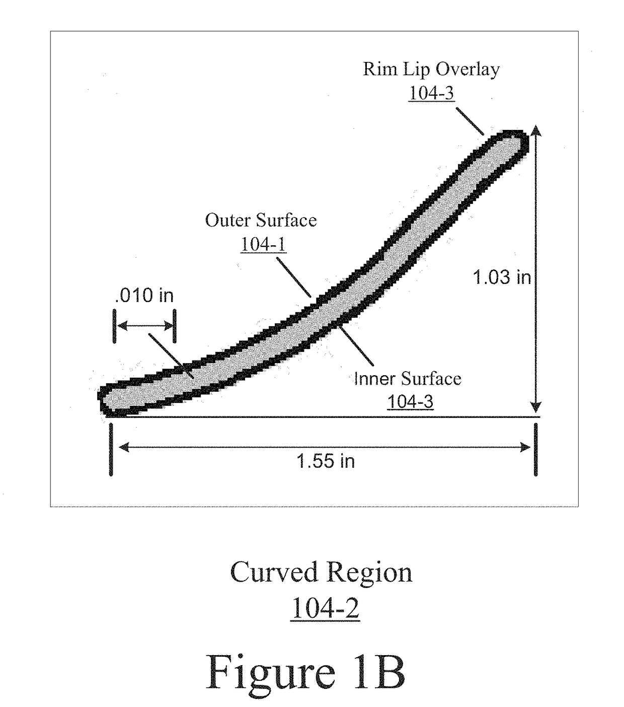
[0009]In one embodiment, the outer region protects the inner tube against pinch flats. In one embodiment, the generally circular flat member comprises a flexible and resilient resin material. In one embodiment, the generally circular flat member is slightly curved in cross section. In one embodiment, the rim further includes a plurality of spokes. In one embodiment, the rim is further operable to accommodate an installable rim guard.
[0010]In one embodiment, the present invention is implemented as a tire for protecting an inner tube. The tire includes a tread portion circumferentially located about an axis of the tire. Also, the tire includes a tire bead, in which the tire bead is coupled to the tread portion by a sidewall and adapted to connect a rim on a wheel. The tire also includes a generally circular flat member integrated into the sidewall and adjacent to the tire bead which includes an inner region adapted to support an inner tube installed within the sidewall and an outer region adapted to extend radially outward from the tire bead to provide protection to the inner tube responsive to the wheel striking an object, the outer region adapted to be positioned between a rim lip of the rim and the inner tube to dull an edge of the rim lip.

Problems solved by technology

When cycling through certain terrains, cyclists often encounter hazards, such as rocks, which have the potential to cause damage to the inner tube, such as causing pinch flats or “snake bites.” For instance, when cycling at high speeds, a bike tire may strike a rock with such force that the casing of the tire pinches the inner tube against the sharp edges of the rim, causing it to puncture with small holes at the point of impact, typically this is considered in the industry to be a pinch flat or snake bite.
Furthermore, when changing an inner tube on a dirt bike often times the tools used to remove or install the inner tube will puncture the tube.
In addition tires for spoked rims are not manufactured with enough rigidity to protect the inner tube from getting a pinch flat.
However, when increasing the level of air pressure, cyclists often have difficulty finding a suitable equilibrium point between a comfortable hardness level for the tire and a suitable air pressure level that minimizes the probability of incurring a pinch flat.
Highly or over-inflated tire also make certain terrain difficult to maneuver while biking.
Furthermore, cyclists may find that increased costs and weight associated with increasing the thickness level of the tire may be too costly and weigh too much to be a viable solution.

Method used


Image

  • Inner tube protective device
  • Inner tube protective device
  • Inner tube protective device

Examples


Embodiment Construction

[0027]Reference will now be made in detail to various embodiments of the invention, examples of which are illustrated in the accompanying drawings. While the invention will be described in conjunction with the following embodiments, it will be understood that the descriptions are not intended to limit the invention to these embodiments. On the contrary, the invention is intended to cover alternatives, modifications and equivalents that may be included within the spirit and scope of the invention as defined by the appended claims. Furthermore, in the following detailed description, numerous specific details are set forth in order to provide a thorough understanding of the present invention. However, it will be readily apparent to one skilled in the art that the present invention may be practiced without these specific details.

[0028]Embodiments of the present invention include a protector element that may be adapted to fit a tire assembly profile associated with conventional motorized...


PUM


Abstract

Embodiments of the present invention provide a novel solution for preventing pinch flats and installation flats incurred by an inner tube as a result of the wheel striking an object. Embodiments are directed to an inner tube protector that fits within a tire and provides mechanical protection to the inner tube against tire strikes. Embodiments may include an inner region adapted to support an inner tube installed around a rim of a wheel. Additionally, embodiments may include an outer region adapted for insertion within and against the rim lip of the rim which provide protection to the inner tube responsive to the wheel striking an object. As such, embodiments may be positioned between the rim and inner tube in a manner that dulls an edge of the rim lip and, thereby, provides protection to the inner tube when compressed against the otherwise sharp edges of the rim lip.

Description

FIELD OF THE INVENTION[0001]Embodiments of the present invention are generally related to the field of inner tube puncture prevention with respect to a tire.BACKGROUND OF THE INVENTION[0002]Within the field of cycling, such as off-road motorcycle riding / racing or bicycle riding / racing relating to mountain / road / regular, cyclists often use tires that have inner tubes beneath the casing of their bike tires to assist in maintaining a desirable level of air pressure while cycling. When cycling through certain terrains, cyclists often encounter hazards, such as rocks, which have the potential to cause damage to the inner tube, such as causing pinch flats or “snake bites.” For instance, when cycling at high speeds, a bike tire may strike a rock with such force that the casing of the tire pinches the inner tube against the sharp edges of the rim, causing it to puncture with small holes at the point of impact, typically this is considered in the industry to be a pinch flat or snake bite. Fur...

Claims


Application Information

Patent Timeline
Patent Type & Authority Patents(United States)
IPC IPC(8): B60C15/00B60C19/12B60B21/12
CPCB60C19/127B60B21/12Y10T152/10657B60B2900/212B60B2360/32
Inventor MERRITT, DAVIDHODSDON, JEFFERYBREEDING, ROBERT
Owner RJ ENG ENTERPRISES
Learn More