Bumper system for vehicle

a bumper system and vehicle technology, applied in the direction of bumpers, elastic dampers, vehicle components, etc., can solve the problems of increasing the cost in proportion to the strength increase, the requirement of property insurance companies, and the increase of the strength, so as to achieve the requirement of vehicle cost and investment cost.

Active Publication Date: 2018-10-23
LOTTE CHEM CORP
View PDF34 Cites 1 Cited by
  • Summary
  • Abstract
  • Description
  • Claims
  • Application Information

AI Technical Summary

Benefits of technology

[0013]According to the present invention, since the crash box that is necessary for the RCAR performance in each area is assembably and separably coupled to the bumper beam, which is integrated in one body to satisfy the low-speed crash regulation, the investment cost and the vehicle cost according to the requirements for each specification may be significantly reduced.

Problems solved by technology

In this case, the required performance of the property insurance companies, which have a great influence on automobile sales, is more demanding than the regulations.
However, when the materials are applied, the costs increase in proportion to the increase in strength.
However, the prior art 1 does not specifically disclose a method for fastening the crash box to a vehicle body, although a member is minimized in damage by matching cross sections of the crash box and the member.
Thus, according to the prior art 1, there is a problem that accessory parts have to be added for fastening the vehicle body, resulting in making it practically difficult to reduce a weight.
In case of the prior art 1, it is difficult to easily induce the abovementioned feature, and also, it is difficult to commercialize the abovementioned feature because it does not take into consideration of an escaping hole of a bolt for towing.
However, in the prior art 2, although a structure in which the crash box is sequentially pressed from a front portion that is a crash site is provided, when considering the bumper barrier test that is added recently, there is a limitation in applying of the prior art 2 as it is.
Also, even if applied, it is expected to increase in weight due to an increase in strength of the bumper beam.

Method used


Image

  • Bumper system for vehicle
  • Bumper system for vehicle
  • Bumper system for vehicle

Examples


Embodiment Construction

[0021]Hereinafter, embodiments of the present invention will be described in detail with reference to the accompanying drawings in such a manner that the technical idea of the present invention may easily be carried out by a person with ordinary skill in the art to which the invention pertains. The present invention may, however, be embodied in different forms and should not be construed as limited to the embodiments set forth herein. In the drawings, anything unnecessary for describing the present disclosure will be omitted for clarity, and also like reference numerals in the drawings denote like elements.

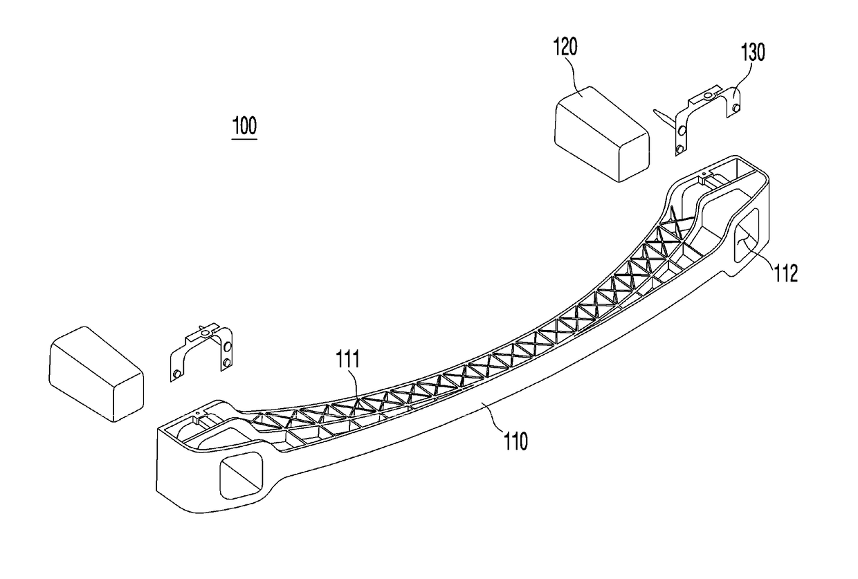
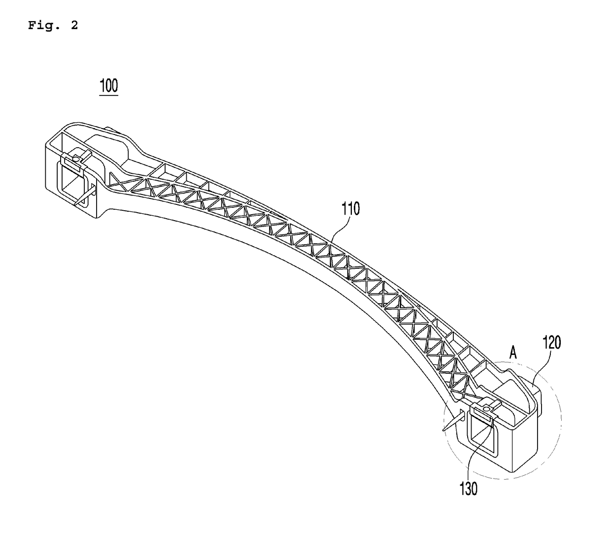
[0022]FIG. 2 is a perspective view of a bumper system for a vehicle according to a preferred embodiment of the present invention, FIG. 3 is an exploded perspective view of the bumper system for the vehicle of FIG. 2, FIG. 4 is a partial enlarged view illustrating a portion A of the bumper system for the vehicle of FIG. 2, and FIG. 5 is a rear perspective view of the enlarged view ...


PUM


Abstract

The present invention relates to a bumper system for a vehicle, and provides a bumper system for a vehicle, the system comprising: a bumper beam which has a fastening hole formed through each end thereof in the forward and backward direction; a crash box which is inserted into the fastening hole of the bumper beam; and a bracket which is fastened to the bumper beam so as to be able to prevent the crash box from being separated. Thereby, the system can meet both low speed crash regulations and RCAR performance.

Description

CROSS REFERENCE TO PRIOR APPLICATIONS[0001]This application is a National Stage Patent Application of PCT International Patent Application No. PCT / KR2015 / 010917 (filed on Oct. 15, 2015) under 35 U.S.C. § 371, which claims priority to Korean Patent Application No. 10-2014-0166094 (filed on Nov. 26, 2014), which are all hereby incorporated by reference in their entirety.TECHNICAL FIELD[0002]The present invention relates to a bumper system for a vehicle, and more particularly, to a bumper system for a vehicle, which satisfies both low speed crash regulation performance and property insurance company requirement performance, which are different from each other by regional groups.BACKGROUND ART[0003]In general, bumper systems for a vehicle are required to satisfy low speed crash tests and property insurance regulatory agency (RCAR, IIHS) tests, which are regulations. In this case, the required performance of the property insurance companies, which have a great influence on automobile sal...

Claims


Application Information

Patent Timeline
Patent Type & Authority Patents(United States)
IPC IPC(8): B60R19/24B60R19/26B60R19/34B60R19/18B60R19/04F16F7/12B60R21/00B60R19/00
CPCB60R19/18B60R19/04B60R19/24B60R19/26F16F7/12B60R19/34B60R2019/262B60R19/00B60R21/00B60R2019/1853B60R19/03B60R2019/1813B60R2019/182B60R2019/1833
Inventor SO, CHOUL WONLEE, MYUNG HOKIM, JUN YOUP
Owner LOTTE CHEM CORP
Why Eureka
Try Eureka