Modular structural component

Active Publication Date: 2018-10-23
CURVOMATIC
View PDF18 Cites 0 Cited by
  • Summary
  • Abstract
  • Description
  • Claims
  • Application Information

AI Technical Summary

Benefits of technology

[0032]The modular component of the present invention is advantageous as curved profiles can be formed quickly and easily without the need for any difficult forming processes. Specifically, curved profiles can be formed by simply sliding a suitable number of suitably sized modular components together and positioning the components in the correct manner. If the curved profile is used to form

Problems solved by technology

Therefore, this method of forming templates, formers, or moulds

Method used


Image

  • Modular structural component
  • Modular structural component
  • Modular structural component

Examples


Embodiment Construction

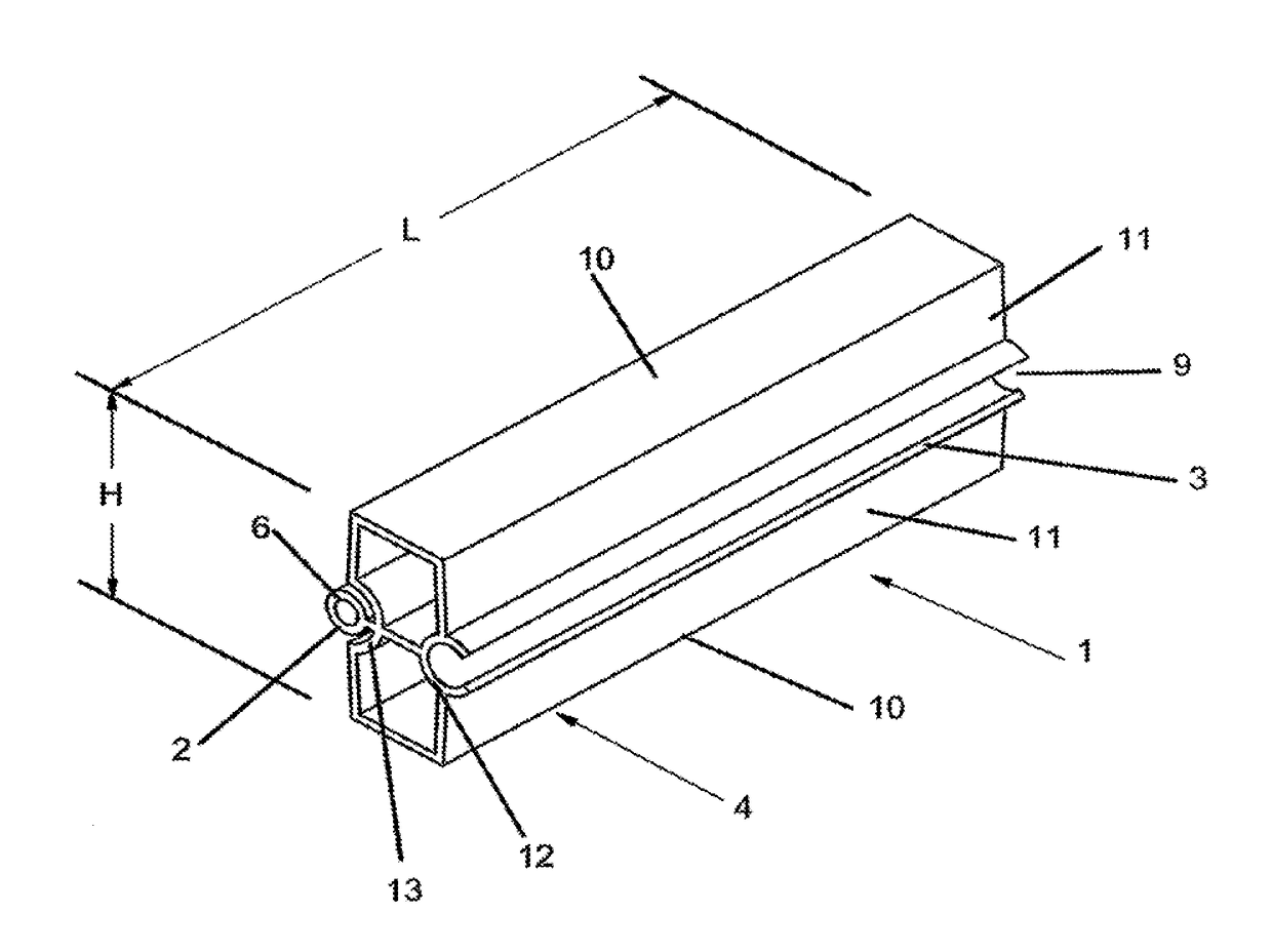
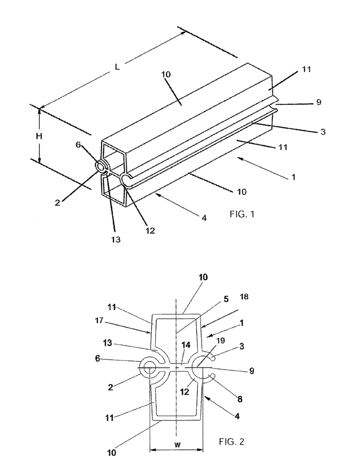
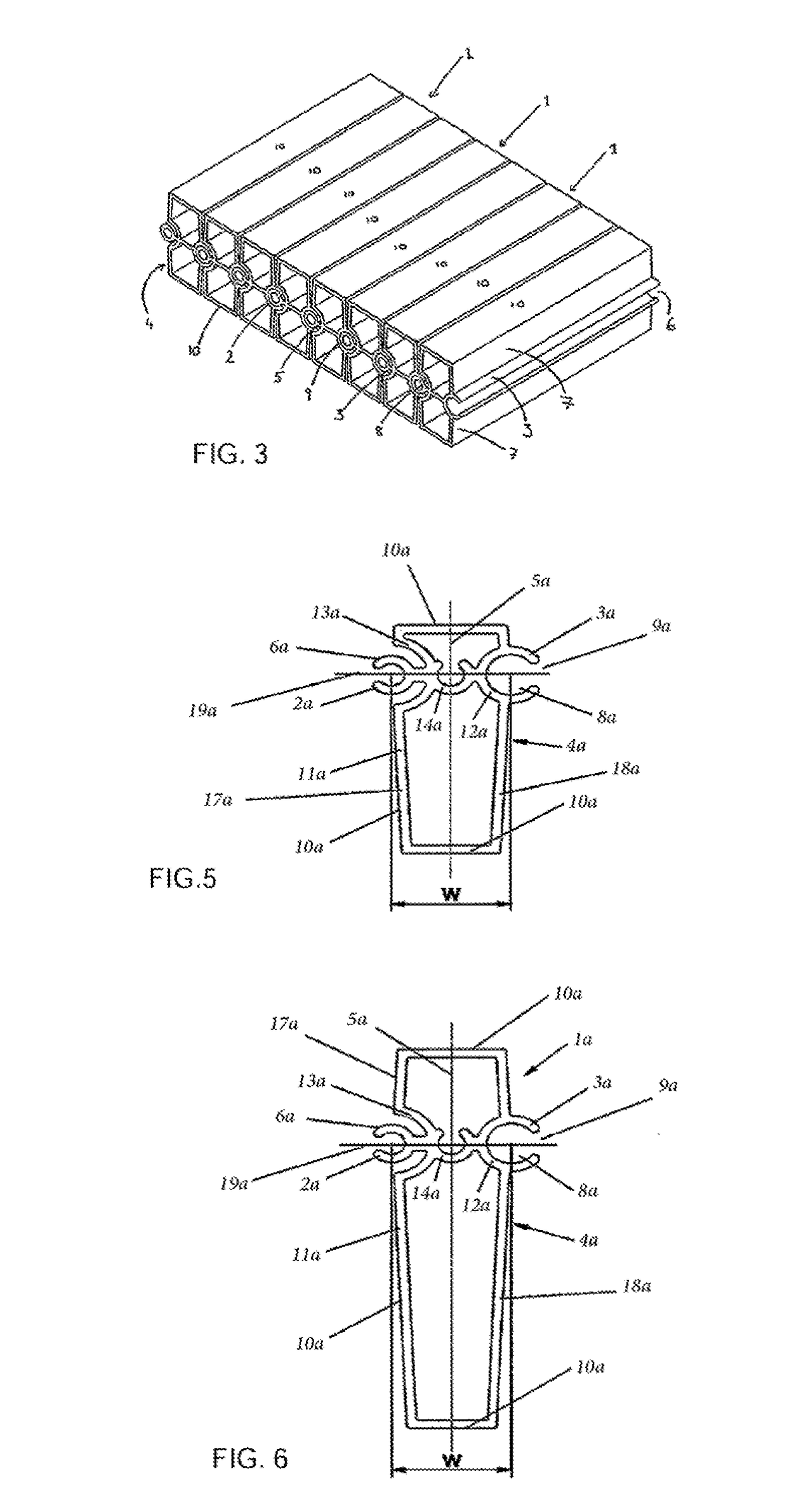
[0052]A preferred embodiment of a component 1 according to the present invention is shown in FIGS. 1 to 4. The modular component 1 comprises an elongate hollow body 4 having two side walls 17 and 18 and two end walls 10. A first attaching means 2 extends along the first side wall 17 of the body 4, and a second attaching means 3 extends along the second side wall 18 of the body 4 for connecting a first component 1 to an identical second modular component 1 as explained below. The component 1 is preferably made by extruding an extrudable material (but could be cast or moulded) and extends longitudinally, and, as can be seen best in FIGS. 1 and 2, has a symmetrical shape about a central plane 19 (see FIG. 2) extending along its length L.

[0053]The first attaching means 2 comprises a longitudinally extending cylindrical spigot 6 and is attached to the body 4 by a mounting portion 7. The mounting portion 7 is substantially planar and is attached to the spigot 6 at a first end and to the b...


PUM


Abstract

A modular component including an elongate hollow body having first and second attaching elements for attaching the modular component to another modular component. The first attaching element is in the form of cylindrical shaped spigot extending along an external surface of a first side wall of the body. The second attaching element is in the form of socket extending along an external surface of a second side wall of the body directly opposite the spigot. The socket has an internal shape that is sized and of a complementary shape of the spigot for receiving a spigot of another modular component. The socket is connected to the spigot by one or more bracing members that extend in a direction from the first side towards the second side between the spigot and the socket.

Description

FIELD OF THE INVENTION[0001]This application is the U.S. national phase of International Application No. PCT / GB2012 / 050476 filed 2 Mar. 2012 which designated the U.S. and claims priority to GB 1103533.4 filed 2 Mar. 2011, and GB 1203680.2 filed 2 Mar. 2012, the entire contents of each of which are hereby incorporated by reference.[0002]This invention relates to modular structural components, and in particular to modular structural components that can be used with like components as curved structural products or as curved formers or templates for manufacturing curved components. A plurality of modular components according to the present invention can be used to create a surface that is gently curved in a first and / or a second direction and substantially linear in a direction that is perpendicular to the first and or second direction.[0003]The co-pending British Patent Application No GB 1103533.4 describes such modular components, and is incorporated by reference in this application.B...

Claims


Application Information

Patent Timeline
IPC IPC(8): F16B17/00F16C11/06E04G11/06E06B9/15
CPCF16C11/06E04G11/062E06B9/15F16B17/00Y10T403/32631E06B2009/1544F16B2200/10E04G9/10E04G11/06E04G11/065
Inventor BURGESS, JAMES
Owner CURVOMATIC
Why Eureka
Try Eureka