
Method for forming braille text and inkjet printer

a technology of inkjet printer and braille text, which is applied in the field of braille text and inkjet printer, can solve the problems of difficult to produce 3d signage in a simple and quick manner, and difficult to produce braille text in a simple and quick manner, and achieve the effect of easy and quick braille tex

Inactive Publication Date: 2018-11-15
ROLAND DG CORP
View PDF5 Cites 1 Cited by
  • Summary
  • Abstract
  • Description
  • Claims
  • Application Information

AI Technical Summary

Benefits of technology

The patent text describes a method for easily creating braille using a photocurable ink and a special inkjet printer. The technique allows for the quick and easy formation of braille text on different surfaces, making it a convenient and efficient tool for visually impaired individuals.

Problems solved by technology

It is difficult to produce braille text in a simple and quick manner because it requires embossing a recording medium, etc.
It is also difficult to produce 3D signage in a simple and quick manner because the production requires machine tools, molding machines, molds, etc.

Method used


Image

  • Method for forming braille text and inkjet printer
  • Method for forming braille text and inkjet printer
  • Method for forming braille text and inkjet printer

Examples


first preferred embodiment

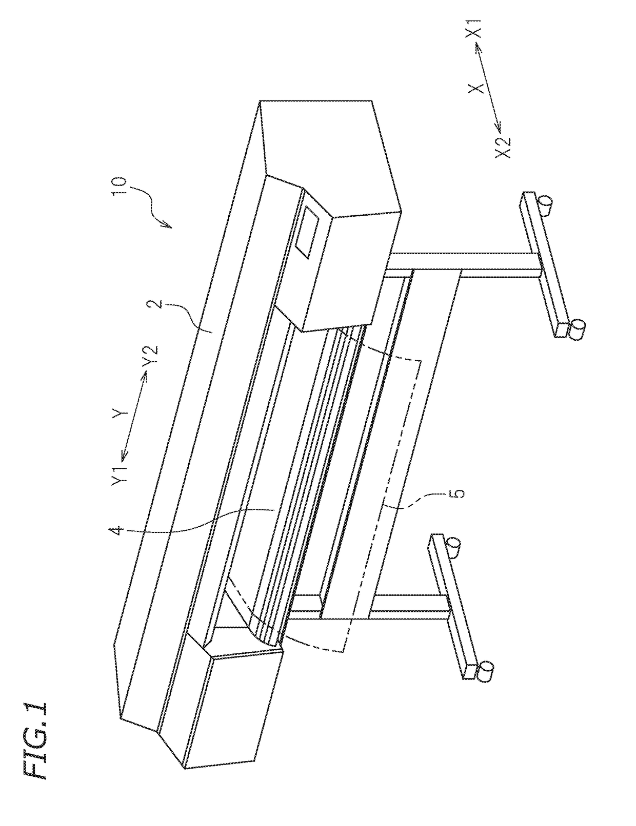
[0024]FIG. 1 is a perspective view of an inkjet printer 10 according to a first preferred embodiment of the present invention. The inkjet printer 10 includes a casing 2, and a platen 4 that supports a recording medium 5.

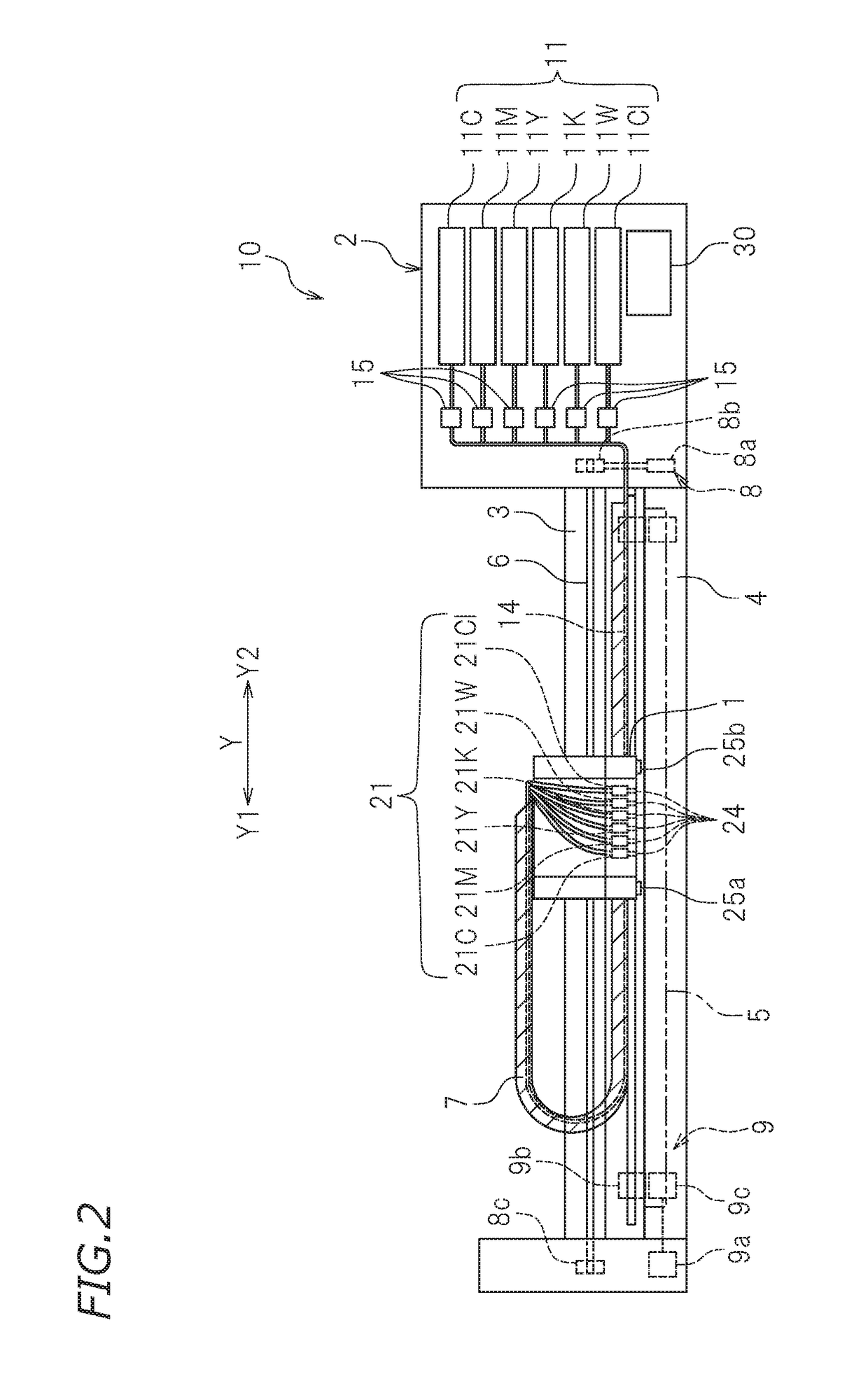
[0025]FIG. 2 is a front view showing the main portion of the inkjet printer 10. The main portion is arranged inside the casing 2. The inkjet printer 10 includes a guide rail 3 provided in the casing 2. The guide rail 3 extends in the primary scanning direction Y and is secured on the left wall and the right wall of the casing 2. A carriage 1 is in engagement with the guide rail 3. The carriage 1 includes an ink discharge head 21 mounted thereon.

[0026]FIG. 3 shows a configuration of the bottom surface of the carriage 1. As shown in FIG. 3, the ink discharge head 21 is mounted on the bottom surface of the carriage 1. The ink discharge head 21 includes six ink heads 21C, 21M, 21Y, 21K, 21W and 21C1. The ink heads 21C, 21M, 21Y, 21K, 21W and 21C1 are arranged in line in ...

second preferred embodiment

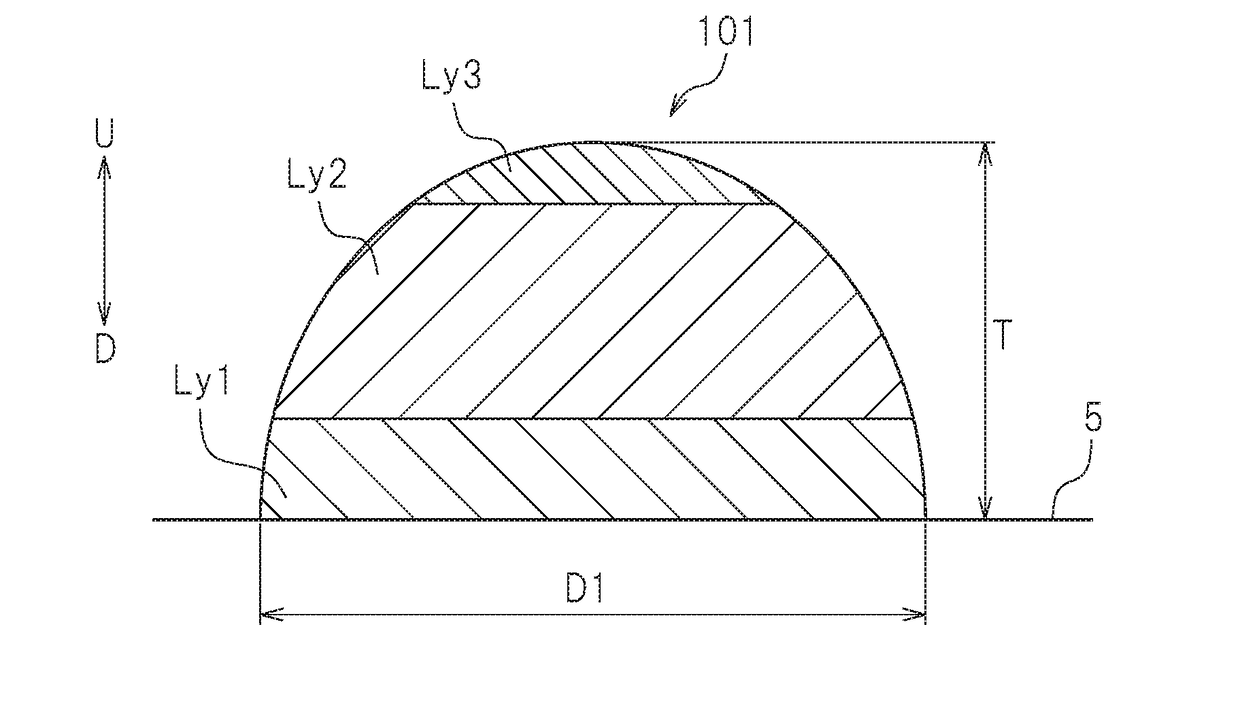
[0071]In a second preferred embodiment of the present invention, the inkjet printer 10 forms a 3D print on the recording medium 5. FIG. 8 shows an exemplary 3D print formed by the inkjet printer 10 according to the present preferred embodiment. The 3D print shown in FIG. 8 is a 3D signage 110. The entirety of the 3D signage 110 shown in FIG. 8 is raised from the recording medium 5. Moreover, non-hatched portions are sunken relative to hatched portions. The 3D signage 110 represents a predetermined sign by the planar shape defined by boundaries between hatched portions and non-hatched portions. The boundaries are preferably rounded. The inkjet printer 10 according to the present preferred embodiment preferably forms a 3D print, such as the 3D signage 110 of FIG. 8, for example. There is no particular limitation on the type of ink used to form a 3D print, but a color ink and a clear ink are preferably used in the example to be discussed below.

[0072]FIG. 9 is a cross-sectional view of ...


PUM

PropertyMeasurementUnit
heightaaaaaaaaaa
heightaaaaaaaaaa
heightaaaaaaaaaa

Abstract

A method for forming braille text on a recording medium, the braille text including cells with one or more dots in each cell, and at least one of the cells includes a plurality of dots therein, includes discharging a photocurable ink onto the recording medium and curing the discharged photocurable ink with light, thus forming a print layer on the recording medium, and discharging a photocurable ink onto the print layer and curing the discharged photocurable ink with light, thus forming one or more additional print layers on the print layer. The braille text has an intra-cell dot-to-dot spacing of about 0.38 mm or more and about 1.32 mm or less.

Description

CROSS REFERENCE TO RELATED APPLICATIONS[0001]This application claims the benefit of priority to Japanese Patent Application No. 2017-092895 filed on May 9, 2017 and Japanese Patent Application No. 2018-056874 filed on Mar. 23, 2018. The entire contents of each application are hereby incorporated herein by reference.BACKGROUND OF THE INVENTION1. Field of the Invention[0002]The present invention relates to a method for forming braille text and an inkjet printer.2. Description of the Related Art[0003]ADA (Americans with Disabilities Act of 1990)-compliant braille text and 3D signage have been used in the art. Braille text is produced by, for example, embossing, and 3D signage is produced by machining, molding, or any other of various techniques.[0004]For example, Japanese Laid-Open Patent Publication No. Hei8-175029 discloses a technique for producing braille text, albeit Japanese braille, by heating a thermal transfer sheet having a thermal expansion layer by means of a thermal head.[...

Claims


Application Information

Patent Timeline
Patent Type & Authority Applications(United States)
IPC IPC(8): B41M3/16B41J11/00B41J13/00B41J2/045B41J3/32B41M7/00B29C64/112B29C64/393
CPCB33Y10/00B33Y30/00B41J3/32B41M3/16B41J11/008B29C64/393B41J2/04586B41J11/002B33Y80/00B41M7/0081B29C64/112B41J13/0027B41J2/2114B41J2/2117B41J11/0021B41J11/00214C09D11/101C09D11/30H04N1/034H04N1/12H04N1/193B41J2/01H04N1/27
Inventor NARIYAMA, YOSHIHIRO
Owner ROLAND DG CORP
Learn More