Prefabricated modular rebar modules and methods of using the same

a technology of modular rebar and rebar cage, which is applied in the field of reinforced concrete, can solve the problems of time-consuming process of installing components on site, long and labor-intensive work, and long rods themselves, and achieves the effect of simple and efficient way

Inactive Publication Date: 2016-04-21
BUZIMKIC EMIN +1
View PDF0 Cites 25 Cited by
  • Summary
  • Abstract
  • Description
  • Claims
  • Application Information

AI Technical Summary

Benefits of technology

[0011]What is desired is a simpler and more efficient way of constructing reinforced concrete structures.
[0012]In an embodiment there is a modular reinforcing steel structure for use in a concrete building wall. The structure may comprise one or more prefabricated, welded modular cages having vertical reinforcing bars. The cages may be prefabricated in an offsite factory where there are the space, tools and workers to quickly and easily create the modular cages. There may be a plurality of continuous ties extending around the vertical reinforcing bars and a plurality of shear ties extending generally horizontally between the vertical reinforcing bars. Each prefabricated welded cage may be sized and shaped for shipping and said structure may be quickly and easily formed onsite from a plurality of said modular cages lapped together.

Problems solved by technology

The fabrication of the re-bar cage according to the detailed design specifications can be slow and tedious work.
The rods themselves can be long and unwieldy.
The entire process of installing the components on site can be time consuming, which in turns increases the costs of the projects.
Delays in the construction of rebar cages can cause significant delays in the entire construction project since the installation of reinforced concrete will often be one of the first steps in a major building project.
Since the installation of the rebar components requires rodworkers and other workers to be present on site, any staffing issues may also cause delays in the overall project.
Constructing rebar structures for raft and transfer slabs onsite is also awkward in that incomplete cage assemblies may lead to partially built cage structures that are shaky and hard to walk on, causing safety issues.
Installation may also be more challenging where confined spaces exist during the construction of the slab layers.
It may also be challenging to place rebar on slabs that are deeper than 1800 mm or approximately 6′ in depth.

Method used


Image

  • Prefabricated modular rebar modules and methods of using the same
  • Prefabricated modular rebar modules and methods of using the same
  • Prefabricated modular rebar modules and methods of using the same

Examples


Embodiment Construction

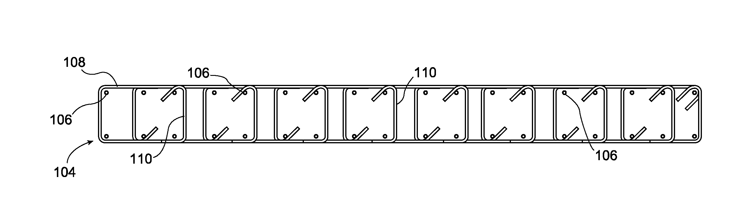
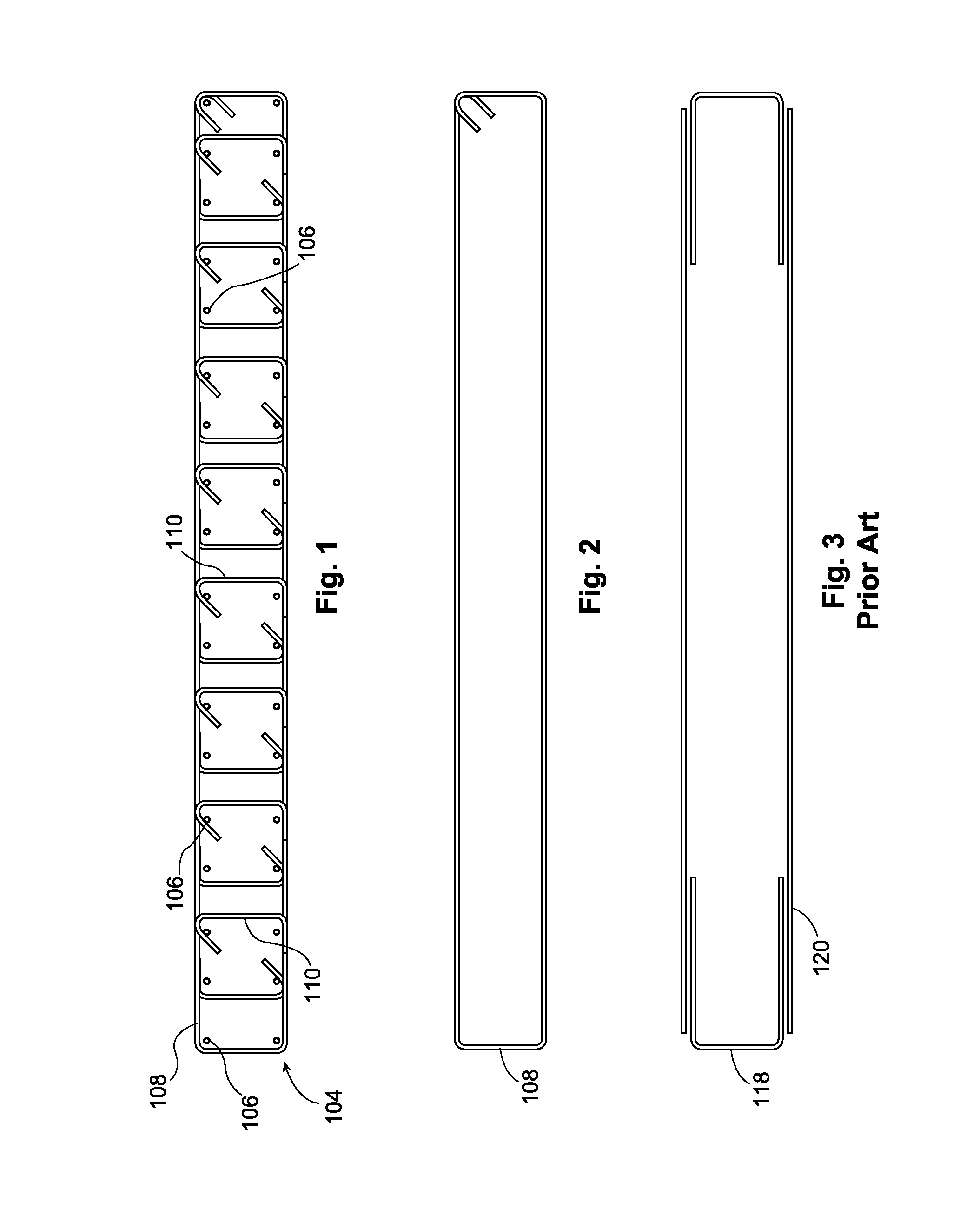
[0037]A prefabricated welded cage 104 is shown in FIG. 1. The prefabricated welded cage 104 includes a number of vertical reinforcing bars 106. A continuous tie 108 extends around the vertical reinforcing bars 106. Although only one continuous tie is shown in FIG. 1, it will be understood that the welded cage 104 includes a plurality of continuous ties 108 which are placed at vertical intervals around the vertical reinforcing bars 106. Preferably, the plurality of continuous ties 108 are spaced at even intervals along the height of the vertical reinforcing bars 106. A. plurality of shear ties 110 extend generally horizontally between the vertical reinforcing bars 106. The welded cage 104 is sized and shaped for shipping.

[0038]The structure of one of the plurality of continuous ties 108 is shown in FIG. 2. The continuous tie 108 shown in FIG. 2 is a single piece of reinforcing steel that forms a closed loop with, for example, ends that overlap.

[0039]In FIG. 3, a prior art design for ...


PUM


Abstract

There is provided a reinforcing steel structure for use in a concrete building wall. The structure includes one or more prefabricated, welded cages having vertical reinforcing bars. A plurality of continuous ties extends around the vertical reinforcing bars and a plurality of shear ties extends generally horizontally between the vertical reinforcing bars. Each welded cage is sized and shaped for shipping and said structure can be formed onsite from a plurality of said cages lapped together. Concrete is added to the reinforcing steel structure to form a concrete building wall.There is also provided a reinforcing steel structure for use in a concrete building transfer or raft slab. The structure includes one or more prefabricated, welded beams. The prefabricated, welded beams have a top beam layer and a bottom beam layer, each having horizontal reinforcing bars, and a plurality of continuous ties extending generally vertically around the top and bottom beam layers. Each welded beam is sized and shaped for shipping and said structure can be formed onsite from a plurality of said beams lapped together. Concrete is added to the reinforcing steel structure to form a concrete building slab.

Description

FIELD OF THE INVENTION[0001]This invention relates generally to the broad field of reinforced concrete and more particularly to the steel, or rebar used to reinforce the concrete. More particularly, this invention relates to methods and apparatus for constructing and installing rebar used in concrete construction.BACKGROUND OF THE INVENTION[0002]Reinforced concrete is a well known and widely used building material which is used in building, bridges, roads, tunnels and other structural construction projects. Essentially the concrete, which is strong in compression but has no strength in tension, is reinforced with steel rods which pass through the zones of tension in the structural element. Engineers design the structural components; calculate the forces which will be generated by the structure, which may be carrying dynamic or static loads or both; and then develop a rebar plan to provide enough rebar reinforcement in the regions of the concrete structure where tension forces may be...

Claims


Application Information

Patent Timeline
Patent Type & Authority Applications(United States)
IPC IPC(8): E04C5/06E04C2/06E04B5/32E04B2/84
CPCE04C5/0609E04B5/32E04C2/06E04B2/84E04C5/0604
Inventor BUZIMKIC, EMINBAUGAARD, KEITH
Owner BUZIMKIC EMIN
Why Eureka
Try Eureka