Biometric sensor with diverging optical element

a technology of optical elements and biometric sensors, applied in the field of optical sensors, can solve the problems of reducing the user experience, affecting the user experience, and difficult to form a flush surface on the face of the device, so as to improve the effect of aperture, reduce blurring effect, and preferentially remove contributions

Active Publication Date: 2018-10-23
WELLS FARGO BANK NAT ASSOC
View PDF113 Cites 6 Cited by
  • Summary
  • Abstract
  • Description
  • Claims
  • Application Information

AI Technical Summary

Benefits of technology

[0008]The present disclosure provides optical biometric sensing devices that include a diverging optical element above an aperture (between the object to be imaged and the aperture) for each sensing element or pixel to enhance the effect of the aperture to preferentially remove contributions of light from object features far from the central axis of the sensing element or pixel. Such embodiments advantageously reduce the blurring effect that occurs when the input object moves further from the sensor. In certain embodiments including an optional “collimator filter”, this use of a diverging optical element (as opposed to none or a converging element) reduces the height or length of the collimator filter that is needed, which can be an advantage in sensor fabrication, including in-display sensing where a longer or taller filter can impact the display image quality.

Problems solved by technology

Unfortunately, conventional optical fingerprint sensors are too bulky to be packaged in mobile devices and other common consumer electronic devices, confining their use to door access control terminals and similar applications where sensor size is not a restriction.
While capacitive fingerprint sensors provide certain advantages, most commercially available capacitive fingerprint sensors have difficulty sensing fine ridge and valley features through large distances, requiring the fingerprint to contact a sensing surface that is close to the sensing array.
It remains a significant challenge for a capacitive sensor to detect fingerprints through thick layers, such as the thick cover glass (sometimes referred to herein as a “cover lens”) that protects the display of many smart phones and other mobile devices.
The need for a cutout makes it difficult to form a flush surface on the face of device, detracting from the user experience, and complicating the manufacture.
The existence of mechanical buttons also takes up valuable device real estate.
However, pinhole cameras suffer from certain disadvantages.
Moreover, the vast amount of light from the object is blocked by the blocking layer and only a small amount of light is transmitted through the aperture.
Thus, image quality may be an issue.

Method used


Image

  • Biometric sensor with diverging optical element
  • Biometric sensor with diverging optical element
  • Biometric sensor with diverging optical element

Examples


Embodiment Construction

[0026]The following detailed description is exemplary in nature and is not intended to limit the invention or the application and uses of the invention. Furthermore, there is no intention to be bound by any expressed or implied theory presented in the preceding technical field, background, summary, brief description of the drawings, or the following detailed description.

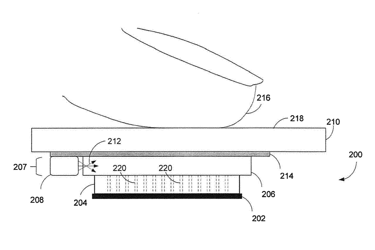
[0027]Turning to the drawings, and as described in greater detail herein, embodiments of the disclosure provide methods and systems to optically image an input object such as a fingerprint. In particular, a method and system is described wherein an optical sensor includes an array of diverging optical elements combined with an array of apertures, or aperture array, which operate as a light conditioning layer, interposed between a light illumination layer and an image sensor array. Transmitted light from the illumination layer reflects from an input object in a sensing region above a cover layer. The reflected light i...


PUM


Abstract

An optical biometric sensor includes an array of light sensing elements, an array of diverging optical elements, and an array of apertures disposed between the array of light sensing elements and the array of diverging optical elements. Light incident on the diverging optical elements within a limited acceptance angle passes through the apertures and towards the light sensing elements and light incident on the diverging optical elements outside of the limited acceptance angle diverges away from the apertures.

Description

FIELD[0001]The present disclosure generally relates to optical sensors, and more particularly to optical sensors using a diverging optical element.BACKGROUND[0002]Object imaging is useful in a variety of applications. By way of example, biometric recognition systems image biometric objects for authenticating and / or verifying users of devices incorporating the recognition systems. Biometric imaging provides a reliable, non-intrusive way to verify individual identity for recognition purposes. Various types of sensors may be used for biometric imaging.[0003]Fingerprints, like various other biometric characteristics, are based on distinctive personal characteristics and thus provide a reliable mechanism to recognize an individual. Thus, fingerprint sensors have many potential applications. For example, fingerprint sensors may be used to provide access control in stationary applications, such as security checkpoints. Fingerprint sensors may also be used to provide access control in mobil...

Claims


Application Information

Patent Timeline
Patent Type & Authority Patents(United States)
IPC IPC(8): G02B3/00G02B27/30G06K9/00G02B5/20
CPCG06K9/00046G02B3/0006G06K9/0008G02B27/30G06K9/0002G02B5/201G02B3/0056G06V40/1318
Inventor LEE, YOUNG SEENWICKBOLDT, PAULGOVE, ROBERT JOHNMACKEY, BOB LEE
Owner WELLS FARGO BANK NAT ASSOC
Why Eureka
Try Eureka