Elastic conductor

a technology of elastic conductors and conductors, applied in the direction of conductors, flat/ribbon cables, printed circuit non-printed electric components association, etc., can solve the problems of increasing the electrical resistance of elastic conductors, and achieve the effect of reducing or preventing an increase in electrical resistance and increasing the path length

Active Publication Date: 2018-10-23
MURATA MFG CO LTD
View PDF12 Cites 0 Cited by
  • Summary
  • Abstract
  • Description
  • Claims
  • Application Information

AI Technical Summary

Benefits of technology

[0006]Preferred embodiments of the present invention provide elastic conductors capable of reducing or preventing an increase in electrical resistance caused by an increase in path length when the elastic conductor is expanded in a prescribed direction.
[0014]According to preferred embodiments of the present invention, it is possible to provide elastic conductors capable of reducing or preventing an increase in electrical resistance caused by an increase in path length when the elastic conductor is expanded in a prescribed direction.

Problems solved by technology

This leads to a fear that the electrical resistance of the elastic conductor may increase.

Method used


Image

  • Elastic conductor
  • Elastic conductor
  • Elastic conductor

Examples


first preferred embodiment

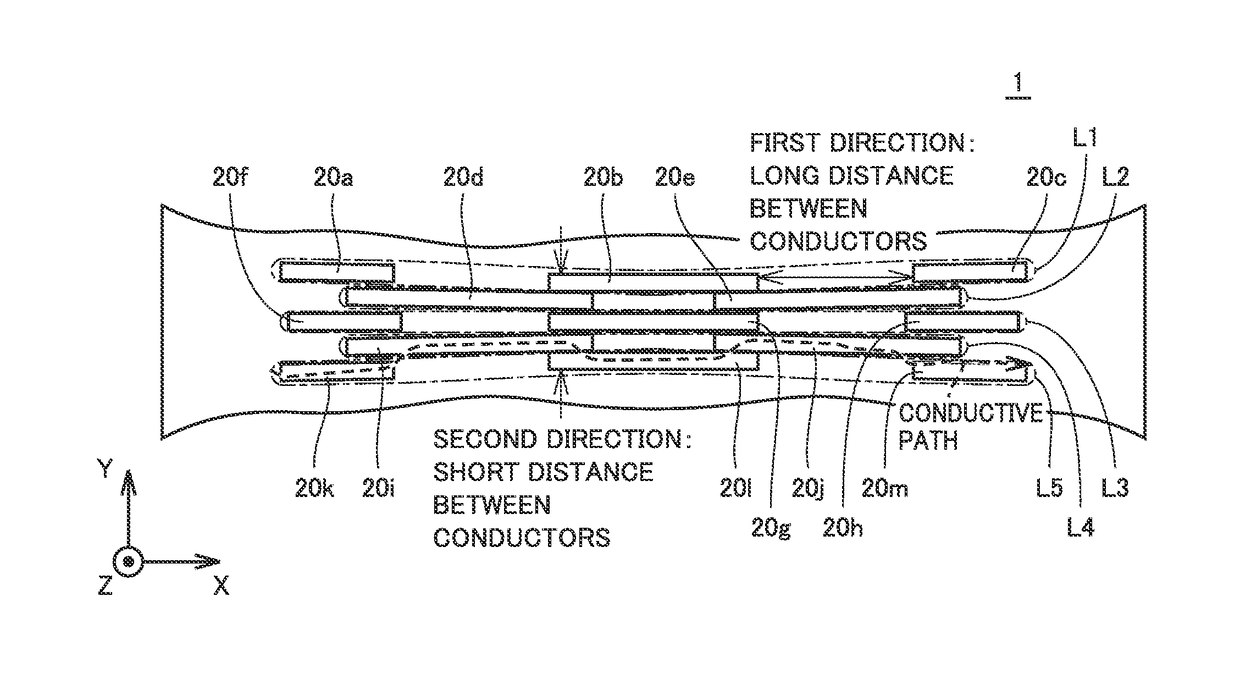
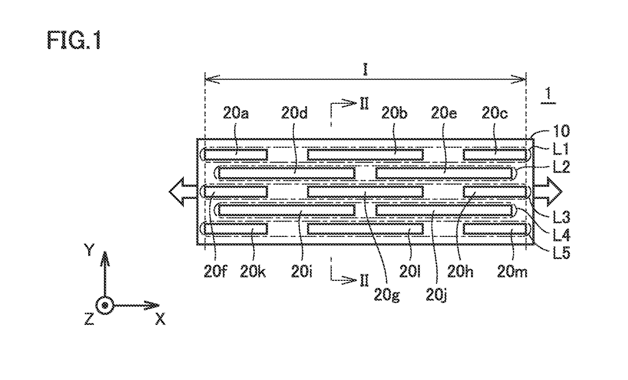
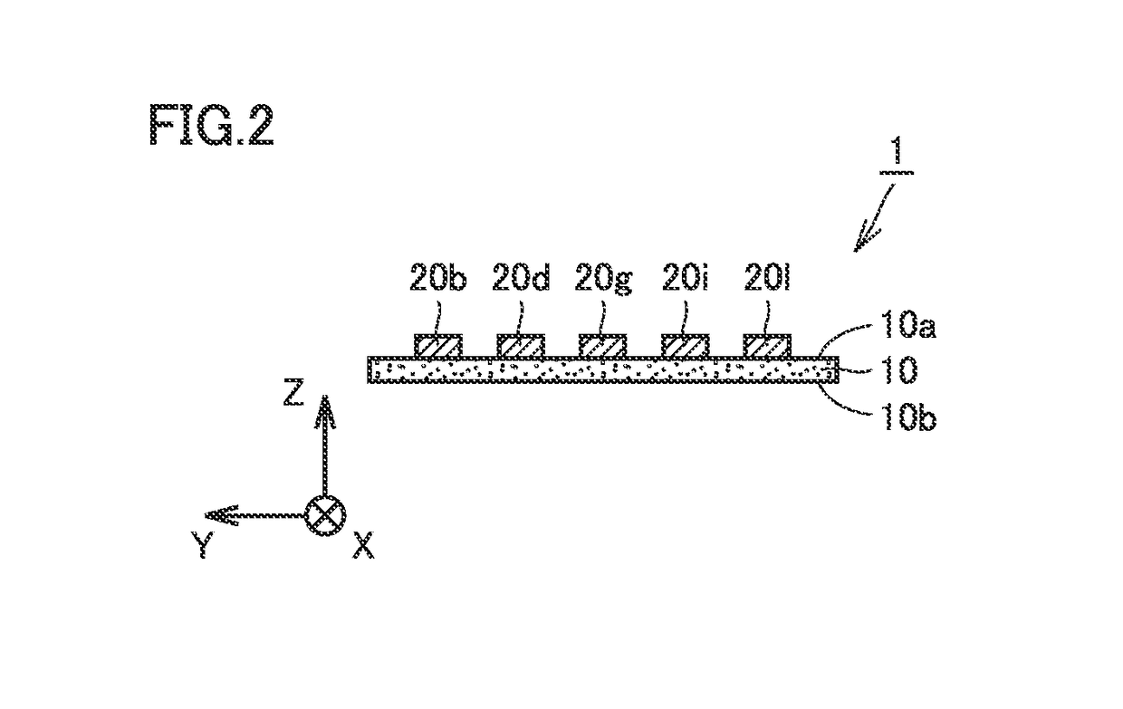
[0046]FIG. 1 is a plan view of an elastic conductor according to a first preferred embodiment of the present invention. FIG. 2 is a cross-sectional view taken along a line II-II in FIG. 1. FIG. 3 is a diagram showing a state in which the elastic conductor according to the first preferred embodiment is tensioned in the first direction. Referring to FIGS. 1 to 3, an elastic conductor 1 according to the present preferred embodiment will be hereinafter described.

[0047]As shown in FIGS. 1 to 3, elastic conductor 1 according to the present preferred embodiment is structured to be changeable between a first state before tensile force acts in a first direction; and a second state in which the tensile force acts in the first direction to cause elastic conductor 1 to be expanded in the first direction. FIGS. 1 and 2 each show the first state of elastic conductor 1, and FIG. 3 shows the second state of elastic conductor 1.

[0048]As shown in FIGS. 1 and 2, elastic conductor 1 includes a stretcha...

second preferred embodiment

[0082]FIG. 9 is a plan view of an elastic conductor according to a second preferred embodiment of the present invention. Referring to FIG. 9, an elastic conductor 1A according to the present preferred embodiment will hereinafter be described.

[0083]As shown in FIG. 9, elastic conductor 1A according to the present preferred embodiment is different from elastic conductor 1 according to the first preferred embodiment in that pattern shapes of a plurality of conductors and electrode portions 21 and 22 are provided.

[0084]The plurality of conductors 20a1 and 20b1 are spaced apart from each other in the second direction perpendicular or substantially perpendicular to the first direction, and to be continuous in at least a partial section I extending in the first direction as seen in the second direction from one end of partial section I to the other end of partial section I in the first direction. At least a partial section I used herein means, for example, a section between electrode porti...

third preferred embodiment

[0091]FIG. 10 is a plan view of an elastic conductor according to a third preferred embodiment of the present invention. Referring to FIG. 10, an elastic conductor 1B according to the present preferred embodiment will hereinafter be described.

[0092]As shown in FIG. 10, elastic conductor 1B according to the present preferred embodiment is different from elastic conductor 1 according to the first preferred embodiment in that pattern shapes of a plurality of conductors and electrode portions 21 and 22 are provided.

[0093]A plurality of conductors 20a2 to 20g2 are spaced apart from each other in the second direction perpendicular or substantially perpendicular to the first direction, and to be continuous in at least a partial section I extending in the first direction as seen in the second direction from one end of partial section I to the other end of partial section I in the first direction.

[0094]The plurality of conductors 20a2 to 20g2 are arranged in a staggered manner. Some conducto...


PUM

PropertyMeasurementUnit
heat resistanceaaaaaaaaaa
lengthaaaaaaaaaa

Abstract

An elastic conductor includes a stretchable base, and conductors each having a longitudinal shape, being arranged on a surface of the stretchable base, and having a lower specific resistance and a higher modulus of elasticity than the stretchable base. In the first state, the conductors are spaced apart from each other in the second direction perpendicular or substantially perpendicular to the first direction, and are continuous in a section extending in the first direction as seen in the second direction from one end of the section to the other end of the section, in which a distance between the conductors adjacent to each other in the second direction in the second state is shorter than a distance between the conductors adjacent to each other in the second direction in the first state.

Description

CROSS REFERENCE TO RELATED APPLICATIONS[0001]This application claims the benefit of priority to Japanese Patent Application No. 2015-162721 filed on Aug. 20, 2015 and is a Continuation Application of PCT Application No. PCT / JP2016 / 071972 filed on Jul. 27, 2016. The entire contents of each application are hereby incorporated herein by reference.BACKGROUND OF THE INVENTION1. Field of the Invention[0002]The present invention relates to an elastic conductor that is changeable between a first state before tensile force acts in a first direction and a second state in which the tensile force acts in the first direction to cause the elastic conductor to be expanded in the first direction.2. Description of the Related Art[0003]Japanese Patent Laying-Open No. 2005-322492 discloses an elastic conductor configured to be stretchable. In the elastic conductor disclosed in Japanese Patent Laying-Open No. 2005-322492, particulate or fibrous magnetic conductors are kneaded into a rubber-like elastic...

Claims


Application Information

Patent Timeline
Patent Type & Authority Patents(United States)
IPC IPC(8): H05K1/02H01B7/08H05K1/18H01B7/06H01B1/22H01B1/24H01B1/02
CPCH05K1/028H01B7/06H01B7/08H05K1/18H05K2201/0129H01B1/023H01B1/026H01B1/22H01B1/24H01B1/02H01R11/01H01B5/16H01B13/008
Inventor SEKIMOTO, YASUYUKI
Owner MURATA MFG CO LTD
Why Eureka
Try Eureka