Clearance enhancer for lower limb prosthesis

a technology of enhancer and lower limb, applied in the field of prosthesis, can solve the problems of difficult and limited use of “high energy” prosthesis, and achieve the effect of high energy foo

Active Publication Date: 2018-11-13
PALMER JEFFREY RAY
View PDF10 Cites 2 Cited by
  • Summary
  • Abstract
  • Description
  • Claims
  • Application Information

AI Technical Summary

Problems solved by technology

However, these necessary dimensions of the prosthetic foot make “high energy” prostheses problematic for persons of smaller stature or amputees with longer residual limbs such as long transfemoral amputees, long transtibial amputees, and Symes amputees, that are limited to a low “build height” for the lower limb prostheses.
These amputees are often limited to choosing a prosthetic knee capable of high activity levels or a prosthetic foot capable of high activity levels, but not both.

Method used


Image

  • Clearance enhancer for lower limb prosthesis
  • Clearance enhancer for lower limb prosthesis
  • Clearance enhancer for lower limb prosthesis

Examples


Embodiment Construction

[0014]For the purposes of promoting an understanding of the principles of the disclosure, reference will now be made to the embodiments illustrated in the drawings and described in the following written specification. It is understood that no limitation to the scope of the disclosure is thereby intended. It is further understood that the present disclosure includes any alterations and modifications to the illustrated embodiments and includes further applications of the principles disclosed herein as would normally occur to one skilled in the art to which this disclosure pertains.

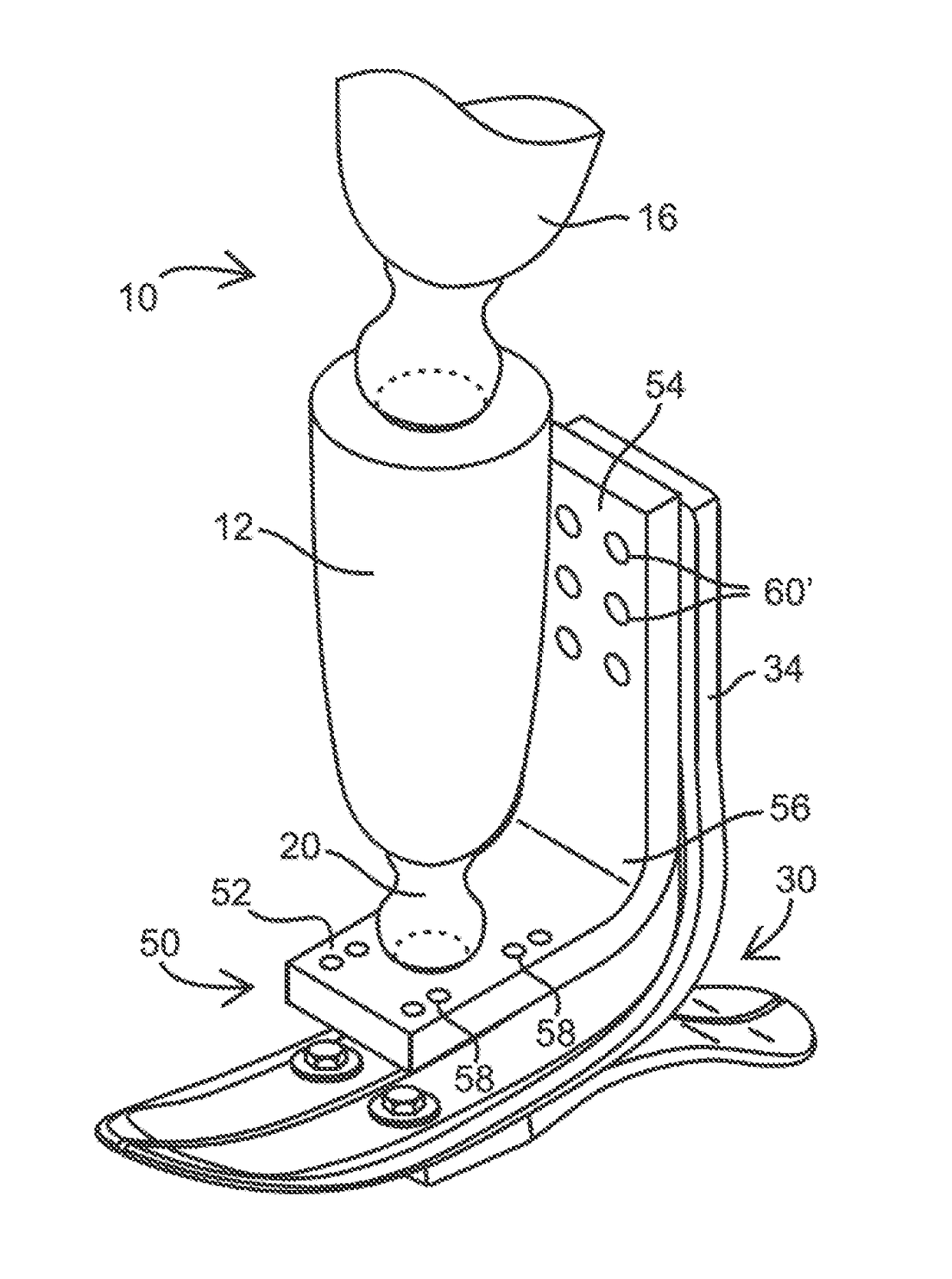
[0015]A clearance enhancer 50 according to the present disclosure is shown in FIGS. 3-4. The clearance enhancer 50 is a generally L-shaped body having a base plate 52, a curved portion 56 and an upper plate 54. The base plate 52 includes a number of mounting openings 58 adapted to receive fasteners for attaching the base plate 52 to the lower end of a transfemoral prosthesis. The base plate 52 may further de...


PUM


Abstract

A lower limb prosthesis for a person is provided that comprises a foot prosthesis having a heel plate for contacting the ground and an ankle plate extending vertically from the heel plate when the heel plate is in ground contact, a leg prosthesis having an upper end portion mountable to the body of the person and a lower end portion, and a clearance enhancer. The clearance enhancer is in the form of a generally L-shaped plate, the plate including a base plate and an upper plate extending generally perpendicularly from the base plate. The base plate is configured to be connected to the lower end of the leg prosthesis. The upper plate includes a number of mounting openings to receive a corresponding number of fasteners for connecting the upper plate to the ankle plate of the foot prosthesis so that the lower portion of the leg prosthesis overlaps the ankle plate of the foot prosthesis.

Description

BACKGROUND[0001]The present disclosure relates to prostheses for the lower limb of a person and particularly to an improvement for the engagement of a prosthetic foot to a lower limb prosthesis.[0002]One form of lower limb prosthesis 10 is shown in FIG. 1 which includes a lower leg or transfemoral pylon 12, connected at its upper end to a prosthetic knee joint 14 and at its lower end to a prosthetic foot 18. The knee joint is connected to a socket 16 adapted for a secure fit to the intact proximal limb. It is understood that the pylon 12 may be part of a total limb prosthesis system. The lower leg pylon 12 is connected to the prosthetic foot 18 by a prosthetic ankle joint 20 as is known in the art.[0003]The foot prosthesis 18 shown in FIG. 1 represents a “low energy” prosthesis in the sense that the foot prosthesis is generally rigid. The prosthesis 18 does not have the ability to flex or the ability to absorb and return energy in flexion in the manner of a physiologically normal fo...

Claims


Application Information

Patent Timeline
Patent Type & Authority Patents(United States)
IPC IPC(8): A61F2/66A61F2/76A61F2/60A61F2/50
CPCA61F2/66A61F2/6607A61F2/76A61F2002/6678A61F2002/5083A61F2002/607A61F2002/6642A61F2002/5021A61F2002/6657
Inventor PALMER, JEFFREY RAY
Owner PALMER JEFFREY RAY
Why Eureka
Try Eureka