Method and apparatus for wheelbarrow front end protection

a technology for front end protection and wheelbarrows, applied in the field of wheelbarrows, can solve problems such as potential damage to surfaces or structures, and damage to surfaces or structures, and achieve the effect of preventing unintentional tipping of wheelbarrows and reducing property damag

a technology for front end protection and wheelbarrows, applied in the field of wheelbarrows, can solve problems such as potential damage to surfaces or structures, and damage to surfaces or structures, and achieve the effect of preventing unintentional tipping of wheelbarrows and reducing property damag

US10124820B2Active Publication Date: 2018-11-13VECTION LTD

Image

  • Method and apparatus for wheelbarrow front end protection
  • Method and apparatus for wheelbarrow front end protection
  • Method and apparatus for wheelbarrow front end protection

Examples


Embodiment Construction

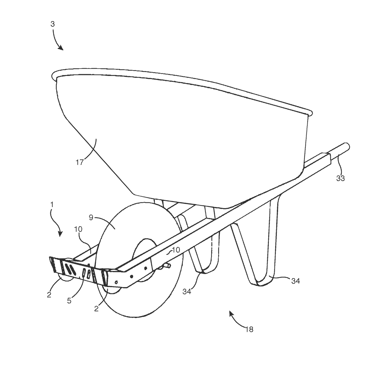
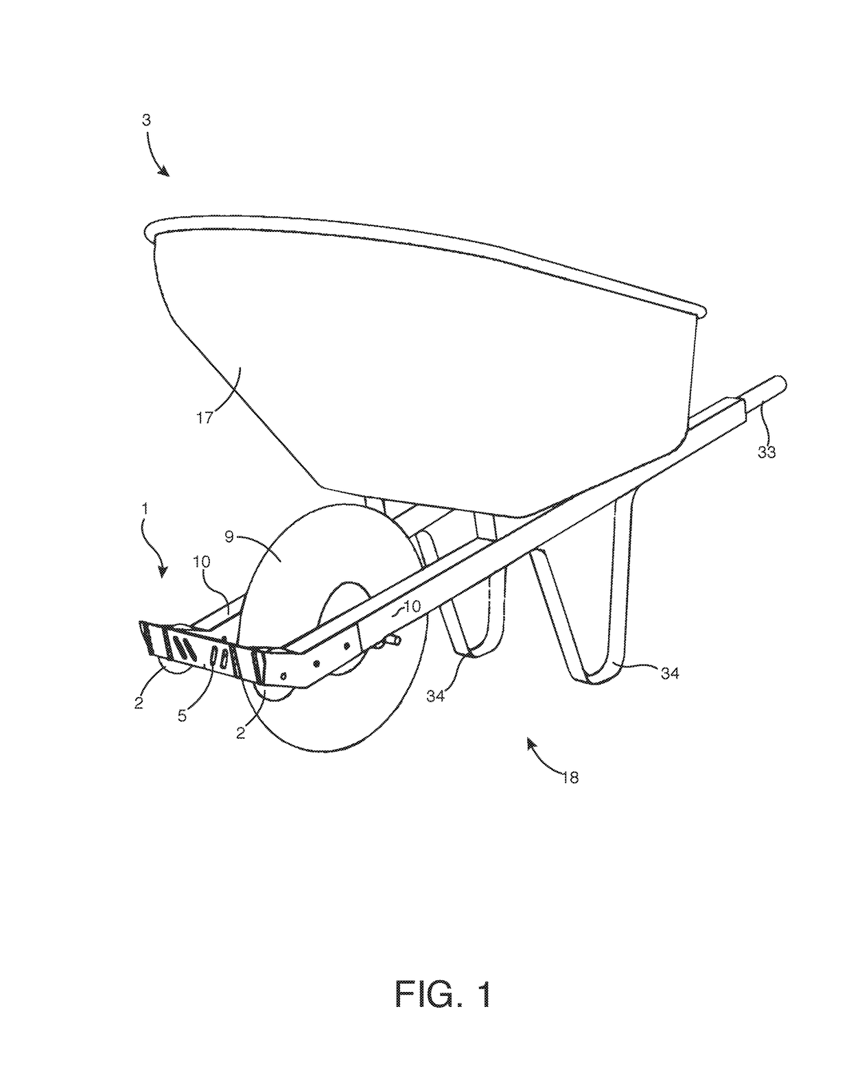
[0041]Embodiments of the invention include a wheelbarrow. In certain embodiments, a wheelbarrow 3 has a pan 17, a frame 18, a main wheel 9, and a bight or bumper. As shown, for example, in FIG. 1 and FIG. 8A, a frame 18 has a main wheel 9 having an axle disposed between two bars 10. A wheelbarrow frame 18 has handles 33 to help to steer the wheelbarrow during use. Legs 34 attached to a lower portion of a wheelbarrow frame 18 keep the wheelbarrow upright. Still referring to FIG. 1 and FIG. 8A, a pan 17 is attached above such frame.

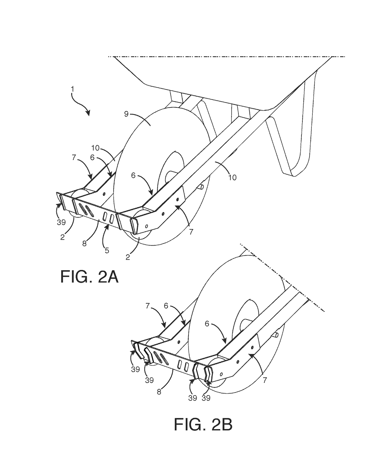
[0042]In certain embodiments of the invention, a bumper is attached to the front portion of a wheelbarrow. An embodiment of a bumper 1 as shown in FIG. 1, an embodiment of a bumper 24 as shown in FIG. 5, an embodiment of a bumper 25 as shown in FIG. 7, and an embodiment of a bumper 28 as shown in FIG. 8A is attached to the front portion of a wheelbarrow 3 in front of a main wheel 9. It will be appreciated that a bumper as disclosed herein can be attached to...


PUM


Abstract

Embodiments of the invention are designed to be improvements over existing wheelbarrows. Certain embodiments comprise a frame, one or more weight-bearing wheels, and a pan. In certain embodiments, a wheelbarrow comprises a bight or a bumper having wheels. The wheels on the bight or bumper are located to the sides of a weight-bearing wheel. In certain embodiments, wheels located on each side of a bight or bumper portion allow a user to maneuver a wheelbarrow up or down a curb, or navigate stairs without causing damage to surfaces. Certain embodiments of the invention allow more efficient unloading of the contents of a wheelbarrow bed. Certain embodiments are designed to retrofit on existing wheelbarrows.

Description

CROSS REFERENCE TO RELATED APPLICATIONS[0001]This application claims benefit to U.S. Provisional Patent Application No. 62 / 315,457, entitled “Method and Apparatus for Wheelbarrow Front End Protection,” filed Mar. 30, 2016, the contents of which are incorporated by reference in its entirety for all purposes.FIELD OF THE INVENTION[0002]Embodiments of the present disclosure generally relate to a wheelbarrow. Embodiments of the present invention are related to a wheelbarrow having a bight or a bumper with wheels. Embodiments of the present disclosure relate to a structure placed on a forward end of a wheelbarrow. Certain embodiments of the invention are located in front of a wheelbarrow wheel. Certain embodiments of the invention are provided as an attachment to existing wheelbarrows. Embodiments of the invention are designed to be improvements over existing wheelbarrows. Certain embodiments comprise a frame, a weight-bearing wheel, and a pan. In certain embodiments, a wheelbarrow compr...

Claims


Application Information

Patent Timeline
13 Nov 2018
Publication
US10124820B2
IPC
B62B1/00; B62B1/18; B62B5/00
CPC
B62B1/186; B62B5/0006; B62B2301/08; B62B2203/05
Inventors
MEYER, MATHEW D.; BEARD, BRYAN