Ornament with backlit film image

a backlit film and image technology, applied in the field of ornaments, can solve the problems of significantly inhibiting commercial viability, complex and expensive manufacture, and none of the prior art devices incorporate backlit film images in the manner, and achieve the effect of facilitating flow-through air convection cooling

Active Publication Date: 2018-11-27
SANTIAGO ROBERT L
View PDF27 Cites 2 Cited by
  • Summary
  • Abstract
  • Description
  • Claims
  • Application Information

AI Technical Summary

Benefits of technology

[0022]More specifically, in one embodiment, the edge accessible slot may include a pair of L-shaped slots and the projection may include a pair of projections in the channel of the end cap. Here, the pair of L-shaped slots may have a size and shape for locking engagement with the respective pair of projections. In an alternative embodiment, the edge accessible slot may include a first cutout extending inwardly from an edge of the cylindrical substrate and a second cutout coupled to and extending away from the first cutout and terminating in a seating cutout having a size and shape for select yielding reception and retention of the projection. Here, the first cutout may include a longitudinal cutout substantially parallel to a longitudinal axis of the cylindrical substrate and the second cutout may include a lateral cutout substantially orthogonal to the longitudinal cutout. At least one of the first or second cutouts may be positioned at an angle relative to the edge. The projection and the edge accessible slot permit selective attachment and removal of the end cap with the cylindrical substrate. The channel may include a substantially rigid material that is otherwise substantially incapable of outwardly flexing.
[0034]In another aspect of this embodiment, the outer lenses may sit flush against the outer frame sections and the inner frame sections may sit flush against the inner lenses. The outer frame and the inner frame may sandwich the outer lenses and the inner lenses therebetween, wherein the inner frame generally forms a plurality of inner open frame sections having a respective illumination region. Additionally, this embodiment may include a plug insertable into one of the upper or the lower caps in non-rotatable and compression-fit engagement therewith. The plug may facilitate drop in reception of a light source within the ornament. The ornament may also include a pyramid-shaped reflector coupled to the lower cap and positioned to reflect light from the light source onto the illumination regions. The backlit film image may be positioned to receive light from the light source through the illumination regions. Lastly, each of the upper and lower channels may include a plurality of detents configured for select snap-fit engagement with a respective plurality of receptacles formed from the outer frame.
[0038]In other features, the ornament may include a domed reflector coupled to the upper retainer cap opposite the lower base and positioned to reflect light from a light source onto the backlit film image. A plurality of feet may couple to the lower base and be positioned proximate the downwardly extending skirt. Here, the feet may extend the lower base off the support surface. To this end, a base vent may be formed in the lower base and a cap vent may be formed in the upper retainer cap. The base vent and the cap vent help facilitate flow-through air convection cooling within the enclosure by providing vented coupling to the ambient air temperatures. This may be particularly useful to help cool the enclosure when a light source is positioned within the enclosure and provides illumination for the backlit films. In one embodiment, the light source may be associated with the lower base in non-rotatable relation therewith. In another aspect of this embodiment, the light source may include a battery powered light coupled to an energy source positioned within the lower base.

Problems solved by technology

The prior art discloses several different types of ornaments that use light to illuminate an image or sign, but such devices tend to be overly complex and expensive to manufacture, which can significantly inhibit commercial viability.
Moreover, none of these prior art devices incorporate a backlit film image in the manner disclosed herein, and as briefly mentioned above.
While this may be desired for the image disclosed in Deal, it is particularly undesirable for full and even illumination of a backlit film image not meant to be distorted depending on the viewing angle.
One problem with Simpson is that the carousel design is overly complex, namely it requires an electric motor, three separate gear assemblies (e.g., a worm drive, idler gear, and 360 degree rotational gear), related axles, linkages, fasteners, rotational friction bearings, etc.
As such, the transparent support must rotate about the washer relative to the insert supporting the light otherwise the Simpson device will not work.
This undesirably precludes hanging the Simpson device from a lighting structure having power lines extending therefrom.
Such permanent affixation is particularly undesirable because the sign cannot be removed and replaced by other signage without completely replacing the entire unit (i.e., both the sign and the supporting substrate or sheet mentioned above).
Chemically bonding the sheets together to form a single sheet of material is undesired because it is not possible to remove and replace for purposes of interchanging the image.
For example, water cannot contact the painted surface because it is inseparably bonded into a single, individual piece of material.
If the two surfaces were separable, weather and moisture would be allowed to contact the printed advertising material and could cause premature wear.
Once engaged, Mainieks states that it is relatively difficult, if not impossible, to remove the upper and / or lower hoops without damaging the lamp shade side wall.
Such permanent affixation is undesirable because it prevents subsequent disengagement of the upper and / or lower hoops for purposes of removing and / or replacing a backlit film image.
Furthermore, elongated rectangular slots that are not edge accessible are undesirable because they require flexation of the upper and / or lower hoops, which destabilizes the structure relative to one that is rigid.

Method used


Image

  • Ornament with backlit film image
  • Ornament with backlit film image
  • Ornament with backlit film image

Examples


Embodiment Construction

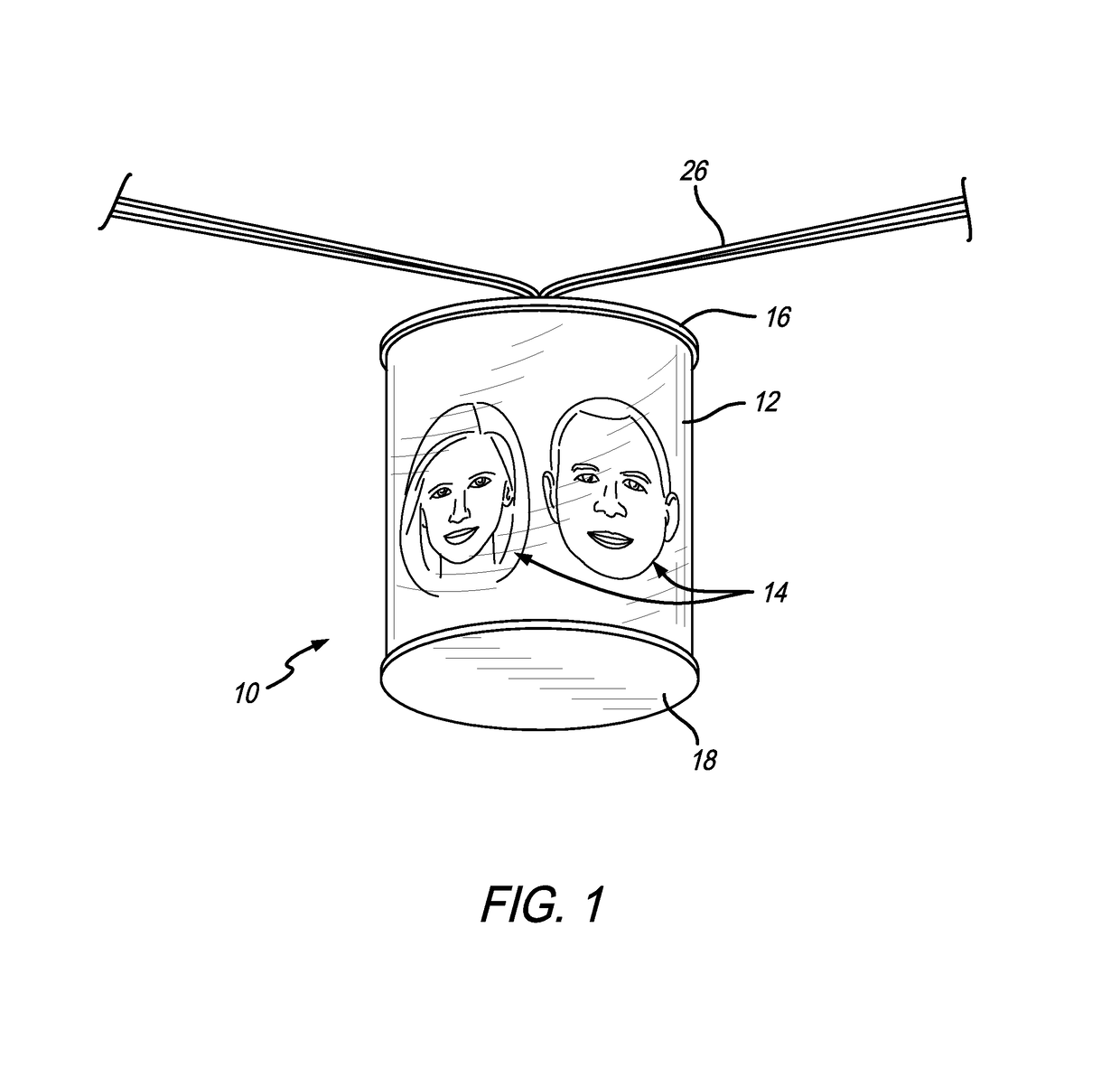
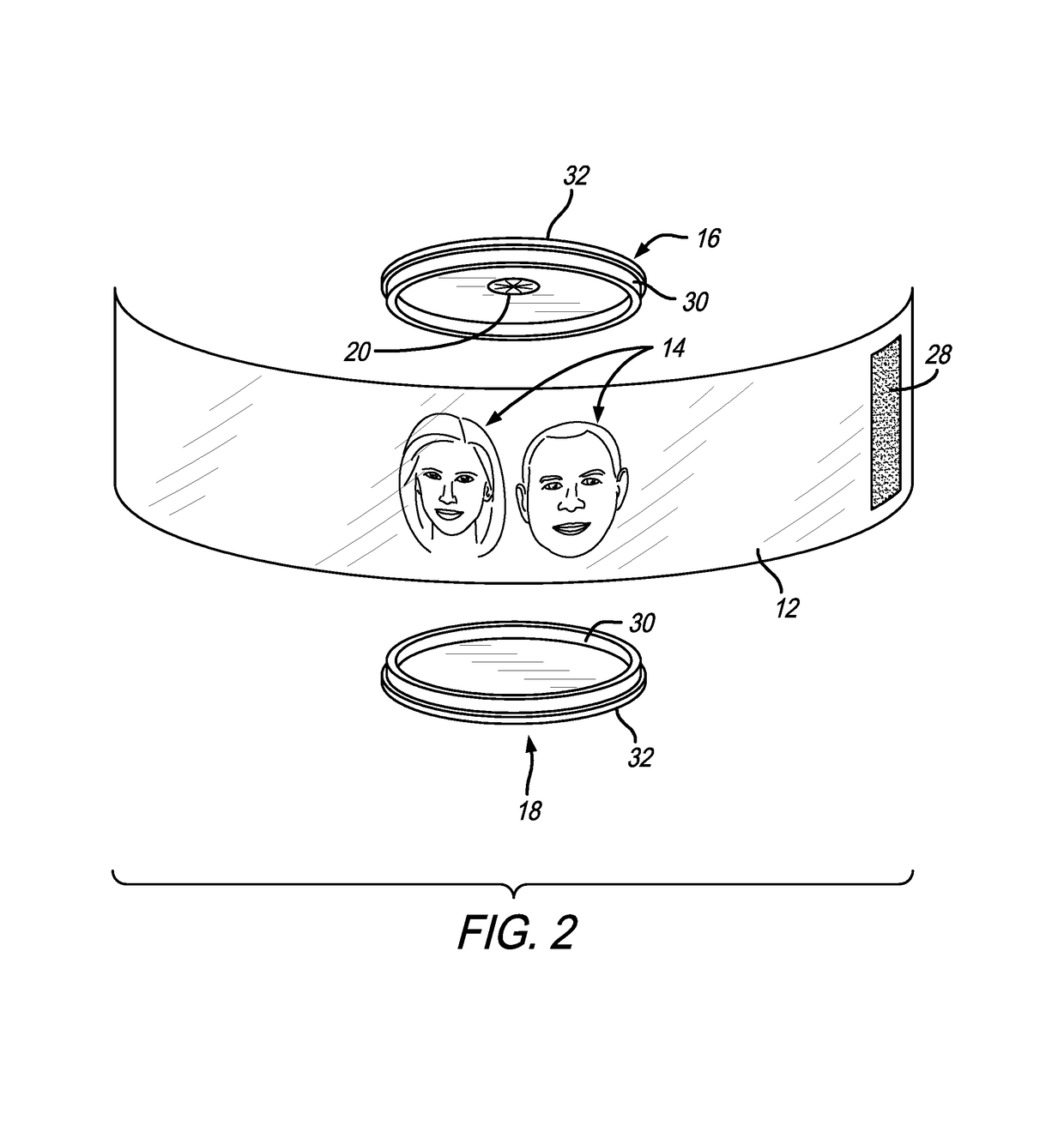
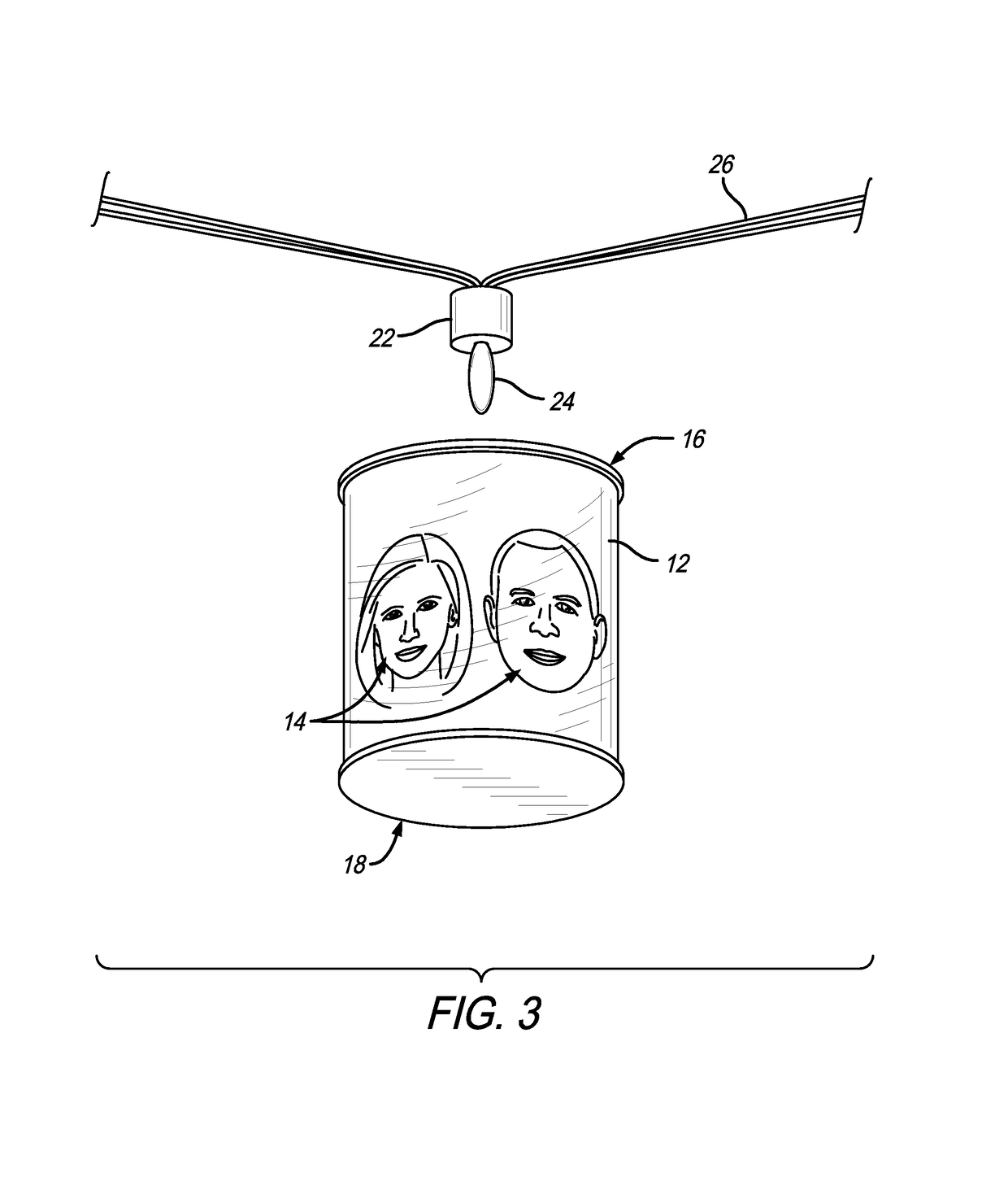
[0086]The present invention relates to an ornament referred to generally in FIG. 1 by the reference numeral 10. The ornament comprises a sheet of backlit film 12 bearing a custom-printed image 14 and rolled into a generally cylindrical shape retained by a pair of generally circular upper and lower retainer caps 16 and 18. At least the upper retainer cap 16 has an opening 20 (FIG. 2) formed therein for slide-fit reception of and engagement with the base 22 or the like of a light source 24 (FIG. 3), such as a small light mounted along the length of an elongated strand 26 of conductors carrying multiple light sources of a type used in a conventional strand of decorative Christmas or holiday lights or the like.

[0087]The sheet of backlit film 12 comprises a sheet of known backlit film material such as that commercially available in rolls of different sheet lengths suitable for use with wide format inkjet media from Eastman Kodak Company, Rochester, N.Y., under the brand name Kodak Premiu...


PUM

PropertyMeasurementUnit
angleaaaaaaaaaa
angleaaaaaaaaaa
angleaaaaaaaaaa

Abstract

An ornament with a backlit film image having a curved substrate with a smooth surface and an at least partially transparent portion viewable therethrough when backlit. The backlit film image includes a flat top surface and a flat bottom surface, wherein one of the flat top surface or the flat bottom surface is positioned flush against the smooth surface of the curved substrate when the backlit film image is removably coupled thereto. A first end cap and a second end cap are configured to receive and retain a portion of the substrate such that the first and second end caps and the substrate support one another into a substantially upright position to define an enclosure. An insert removably engages one of the first or second end caps and includes an aperture having a size and shape for compression-fit engagement with a light source.

Description

BACKGROUND OF THE INVENTION[0001]This invention relates generally to an ornament including backlit film bearing a custom image formed into a generally cylindrical shape and retained in the form of a hollow cylinder by circular upper and lower retainer caps. At least one of these retainer caps, such as the upper cap, has a small opening formed therein to receive a light source, such as a light mounted along an elongated strand of the type used for Christmas decorations.[0002]Backlit film is generally known in the art for use in printing a custom image onto the film, and then backlighting the printed film to illuminate the custom image. Such backlit film is often used in the preparation of posters and the like of generally planar shape. Backlit film has recently become available for use in home printing applications, such as by use of an inkjet printer or the like for printing of a wide variety of home artwork, such as individual photographs of friends and relatives. Exemplary backlit...

Claims


Application Information

Patent Timeline
Patent Type & Authority Patents(United States)
IPC IPC(8): A47G33/08F21S4/10G09F13/04F21V7/04F21V1/22F21V1/14F21V1/04F21V3/02F21V29/83F21V17/10F21V17/16F21V19/00F21L4/08F21W121/00F21W121/04
CPCF21S4/10F21V1/04F21V1/143F21V1/22F21V3/02F21V7/045G09F13/0413A47G33/0836G09F2013/0481A47G2033/0827F21L4/08F21V7/04F21V17/104F21V17/164F21V19/006F21V29/83F21W2121/00F21W2121/04G09F13/0481
Inventor SANTIAGO, ROBERT L.
Owner SANTIAGO ROBERT L
Why Eureka
Try Eureka