Method and apparatus for CDMA signal reception

a signal and signal processing technology, applied in the field of signal reception methods, can solve the problems of high path of reception level, inability to properly achieve despatch, and so as to enhance the detection accuracy of paths and avoid deterioration of reception characteristics.

Inactive Publication Date: 2007-11-06
NEC CORP
View PDF25 Cites 9 Cited by
  • Summary
  • Abstract
  • Description
  • Claims
  • Application Information

AI Technical Summary

Benefits of technology

[0024]It is an object of the present invention to provide a CDMA reception method capable of obviating deterioration of the reception characteristics caused by a variation of timing while enhancing a detection accuracy of the paths.
[0025]It is another object of the present invention to provide a CDMA reception device capable of obviating a deterioration of the reception characteristics caused by a variation of timing while enhancing a detection accuracy of the paths.
[0032]In the present invention, isolating the averaging process of the path levels from the update of the path timing enables updating the path timings at, for example, every reception period of radio signals while enhancing the accuracy of detecting the paths. As a result, the present invention offers an advantage of allowing satisfactory follow-up to the timing variation while maintaining a high accuracy of detecting the paths thereby obviating deterioration of the signal-reception characteristics caused by the timing variation. In other words, since the CDMA signal-reception method and the CDMA signal-reception device according to the present invention, when performing the detection of the synchronization timing, calculate path timings at periods of receiving radio signals to update the allocation to fingers at the periods of receiving radio signals, and also calculate, at the periods of receiving the signals, path levels to compute averages of the calculated path levels and the path levels calculated in the past to realize an accurate detection of the paths, it is feasible to maintain the follow-up characteristics to the timing variation while enhancing the accuracy of detecting the paths.
[0033]Consideration is now made with an example of signal-reception path timings as shown in Table 1, which shows the case of averaging delay profiles over every three signal-reception periods and, on the basis of the averaged delay profile, determining the paths to be allocated to fingers for the subsequent three signal-reception periods. The table illustrates that the path timing is updated only once every three signal-reception periods in the prior art while the CDMA reception device according to the present invention updates the path timing every signal-reception period thereby enabling improved follow-up to the timing variation. Consequently, it is enabled to prevent the deterioration of the signal-reception characteristics caused by the timing variation properly as compared to the conventional techniques of implementing a add-and-average process of delay profiles, as illustrated in FIGS. 2A to 2D.

Problems solved by technology

As a spreading code, a pseudo-random code sequence, for example, has been typically used, and if the synchronization in the spreading codes is not established between the sending and receiving ends, the despreading will not be properly achieved.
A case may happen, however, that the state of propagation between a sending end and a receiving end varies from time to time or that, when at least one of the sending and receiving ends moves, for example, a new path suddenly comes out or the path of a high reception level, which has so far existed, is suddenly lost, as the moving end moves.
In this approach, the cases may happen that the values of the correlation levels in the delay profile widely change under the environment in which, for example, multipath fading occurs, causing changeovers in the synchronization timing to be allocated to a certain finger and in turn causing frequent changeovers of the reception paths.
Such frequent changeovers of the reception paths significantly deteriorate the reception characteristics of the CDMA reception system.
Since use of the averaged delay profile, however, cannot be promptly adaptive to the cases such as where a new intense path comes out and where a path that has so far existed is lost, a case could adversely occur that the quality of the reception signals is degraded.
However, since the path timing cannot be updated during the process of averaging the delay profile, it has been impossible to follow the timing variations, which have caused deterioration of the characteristics.
For example, only 0.7 chips of out-of-synchronization causes a significant deterioration in the reception characteristics (e.g., the reception sensitivity, the S / N ratio).
It is not necessarily an optimum approach from the view of exact accordance of the synchronization timings to extract the path timings from the averaged delay profile.
As a result, effecting the despread through the use of the timing of 10.5 chips causes degradation of the reception characteristics such as a deterioration of the reception sensitivity.
Thus, sole averaging of delay profiles involves also averaging with respect of the path timing, thereby deteriorating the follow-up characteristics to the variations of timings.
As described above, the conventional CDMA receivers are problematic in that effecting the path detection on the basis of an averaged delay profile makes it impossible to follow up the variation of the path timing causing the deterioration of the characteristics, while improving the accuracy of detecting the paths.

Method used


Image

  • Method and apparatus for CDMA signal reception
  • Method and apparatus for CDMA signal reception
  • Method and apparatus for CDMA signal reception

Examples


first embodiment

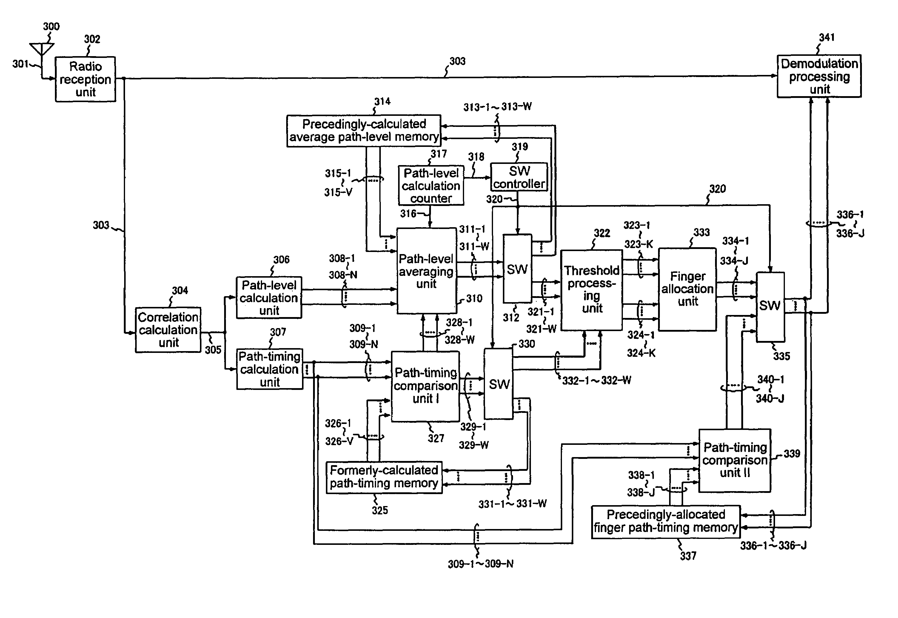
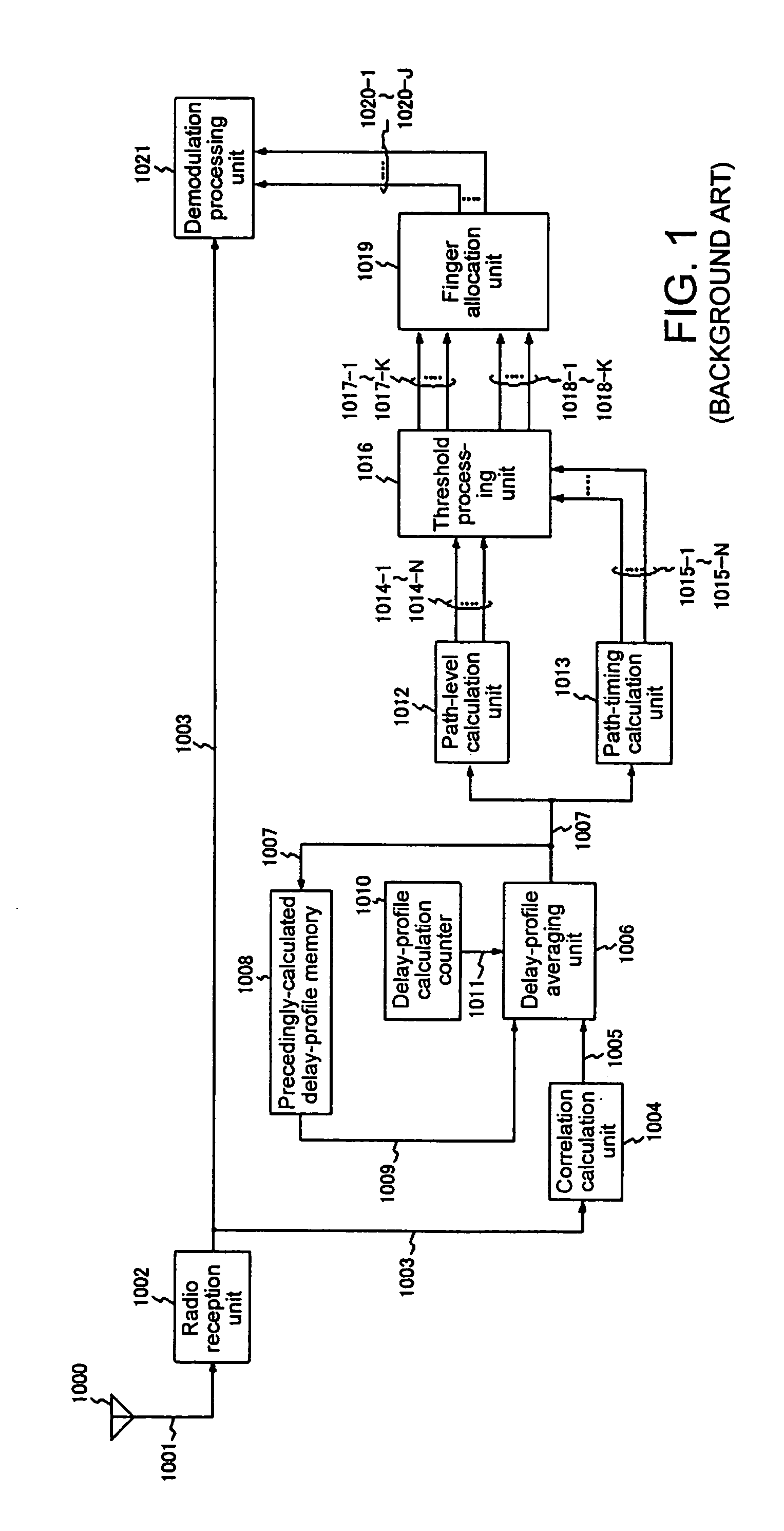
[0041]The CDMA reception device according to the present invention illustrated in FIG. 3 is, in order to separately execute the averaging process of path levels and the update of path timings, provided with: antenna 100 for receiving a radio signal transmitted from a sending end; radio reception unit 102 for converting a received radio signal into a baseband signal 103; correlation calculation unit 104 for calculating the correlation value of the baseband signal 103 and providing a delay profile 105; path-level calculation unit 106 for calculating N path levels 108-1 to 108-N on the basis of delay profile 105 provided from correlation calculation unit 104; and path-timing calculation unit 107 for calculating N path timings 109-1 to 109-N on the basis of delay profile 105. The number N is a natural number. A correlation calculation unit provided with a sliding correlator and a matched filter can be employed as correlation calculation unit 104 as with the conventional CDMA reception d...

second embodiment

[0070]Explanation is next presented regarding the CDMA reception device according to the present invention.

[0071]While the CDMA reception device shown in FIG. 3 effects the averaging of path levels through the use of a forgetting factor, the CDMA reception device of the second embodiment shown in FIG. 5 is useful in the case where moving averaging is applied for the averaging process of the path levels. The device shown in FIG. 5 differs in construction from device shown in FIG. 3 in that precedingly-calculated average path-level memory 116 is replaced with path-level memory 216 and precedingly-calculated path-timing memory 118 is replaced with path-timing memory 218. For reference, the meanings of path numbers N, K and J in the device shown in FIG. 5 are the same as those in the device shown in FIG. 3.

[0072]The CDMA reception device shown in FIG. 5 is provided with antenna 200 for receiving a radio signal; radio reception unit 202 for converting received radio signal 201 to baseban...


PUM


Abstract

The N peaks are selected from a delay profile in order starting from the highest peak involved in the delay profile, the path level and path timing are determined for each of the selected peaks, and the identical paths individually responsible for different delay profiles are detected by comparing the path timings calculated for the preceding time and the path timings calculated for the present time. Based of the path levels calculated for the preceding time and the path levels calculated for the present time, averaged path levels are computed on a path-by-path basis for the present time, a predetermined threshold is applied to the computed average path levels, and the paths to be allocated to the fingers are selected. Of the path timings that have been obtained for respective selected paths, the latest path timings are allocated to the fingers as synchronization timings.

Description

BACKGROUND OF THE INVENTION[0001]1. Field of the Invention[0002]The present invention relates to a signal reception method and a signal reception apparatus compliant with the CDMA (code division multiple access) communication scheme.[0003]2. Description of the Background Arts[0004]In a CDMA communication system, a sending end spreads transmission data over a wideband spectrum range using a predetermined individual spreading code assigned in advance, and the receiving end despreads (i.e., demodulates) the reception signal through the use of the identical spreading code. As a spreading code, a pseudo-random code sequence, for example, has been typically used, and if the synchronization in the spreading codes is not established between the sending and receiving ends, the despreading will not be properly achieved.[0005]Generally, the radio propagation route between a sending end and a receiving end is not necessarily single, and a plurality of the propagation routes can be present due t...

Claims


Application Information

Patent Timeline
Patent Type & Authority Patents(United States)
IPC IPC(8): H04J3/06H04B1/707H04B1/7117H04B7/216
CPCH04B1/7117H04B1/7113
Inventor OURA, SATOSHI
Owner NEC CORP
Why Eureka
Try Eureka