Radio communication apparatus, radio communication method, antenna apparatus and first duplexer

a radio communication and antenna technology, applied in the direction of polarised antenna unit combinations, electromagnetic wave modulation, volume compression/expansion, etc., can solve the problems of low standby time performance, high receiving signal level, and increase the current consumption of the control circuit for switching modes. , to achieve the effect of reducing the deterioration of the transmitting signal on simultaneous transmission and reception, and reducing the deterioration of the reception

Inactive Publication Date: 2007-07-17
PANASONIC CORP
View PDF17 Cites 14 Cited by
  • Summary
  • Abstract
  • Description
  • Claims
  • Application Information

AI Technical Summary

Benefits of technology

[0019]In consideration of the above problems, an object of the present invention is to provide the radio communication apparatus and radio communication method capable of reducing deterioration of reception on simultaneous transmission and reception without reducing standby time.
[0021]A further object of the present invention is to provide the radio communication apparatus and radio communication method capable of reducing the deterioration of the transmitting signal on simultaneous transmission and reception.
[0099]The 18th aspect of the present invention is the radio communication apparatus according to the 17th aspect of the present invention, wherein said sixth duplexer does not substantially pass the differential signal in the frequency band of said receiving signal but passes the single-phase signal in the frequency band of said transmitting signal substantially without a loss.
[0106]According to the present invention, it is possible to provide the radio communication apparatus and radio communication method in which the deterioration of the reception on simultaneous transmission and reception is reduced.
[0107]According to the present invention, it is also possible to provide the antenna apparatus capable of outputting the receiving signal as the differential signal.
[0108]According to the present invention, it is also possible to provide the radio communication apparatus and radio communication method in which the deterioration of the transmitting signal on simultaneous transmission and reception is reduced.

Problems solved by technology

For that reason, standby time performance is little improved in the case of frequently switching transmission on and off.
Current consumption of a control circuit for switching the modes also increases.
In addition, in the case where the radio communication apparatus is near the base station, a receiving signal level becomes high and transmitting signal power becomes low.

Method used


Image

  • Radio communication apparatus, radio communication method, antenna apparatus and first duplexer
  • Radio communication apparatus, radio communication method, antenna apparatus and first duplexer
  • Radio communication apparatus, radio communication method, antenna apparatus and first duplexer

Examples


first embodiment

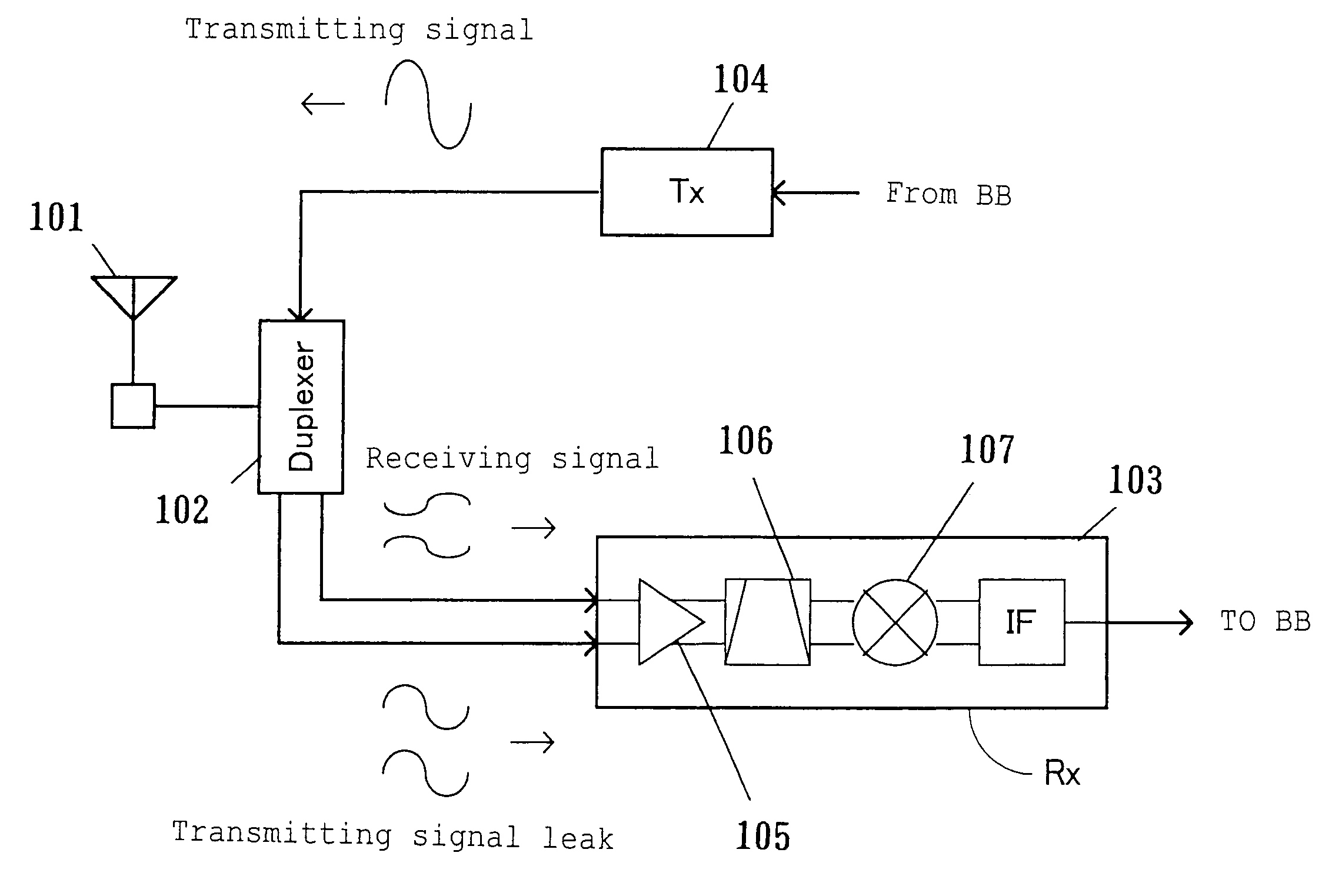
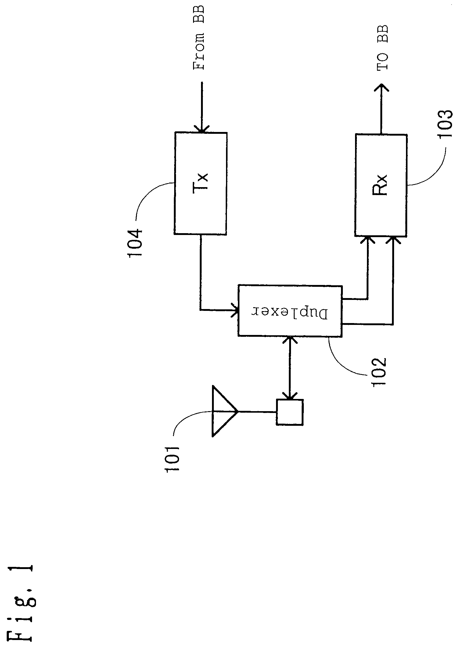
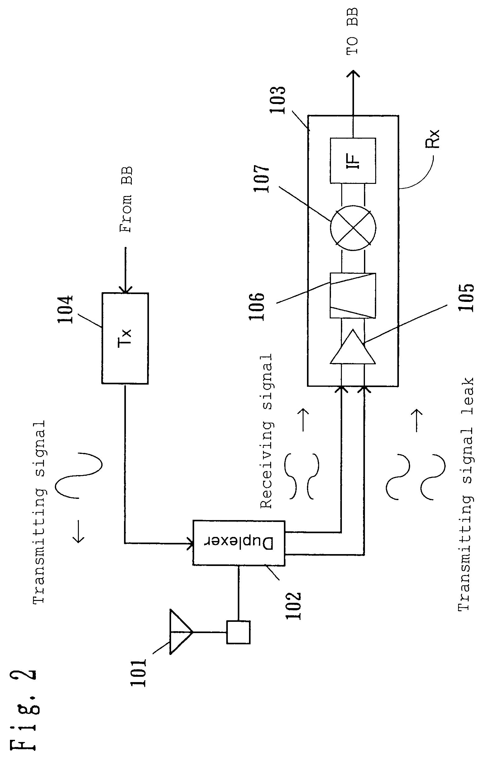
[0164]FIG. 1 is a circuit diagram of a radio communication apparatus related to a first embodiment of the present invention. In this diagram, reference numeral 101 denotes a single-phase input-output antenna corresponding to an antenna of the present invention as an example, 102 denotes a duplexer (antenna sharing apparatus) of which transmission input terminal is a single-phase input type, antenna input-output terminal is a single-phase input-output type, and receiving output terminal is a balanced output type as an example of a duplexer of the present invention, 103 denotes a receiving circuit of differential input as an example of a receiving apparatus of the present invention connected to the balanced outout terminal and having a circuit in which a gain of a signal of a differential component is higher than that of a signal of an in-phase component, or a loss of the signal of the differential component is lower than that of the signal of the in-phase component, and 104 denotes a...

second embodiment

[0192]FIG. 11 is a circuit diagram of the radio communication apparatus related to a second embodiment of the present invention. In FIG. 11, the same components as those shown in FIG. 1 are given the same symbols, and a description thereof will be omitted. In FIG. 11, reference numeral 902 denotes a duplexer of which terminals are single-phase input-output, and 905 denotes a phase shifter of single-phase input and balanced output which outputs the signals in the frequency band of the receiving signals as the differential signals and outputs the signals in the frequency band of the transmitting signals as the in-phase signals. Here, the duplexer of the present invention described in the first embodiment is corresponding as an example to the duplexer 902 and the phase shifter 905.

[0193]As for the radio communication apparatus shown in FIG. 11, the radio frequency signal transmitted from the base station is received by the antenna 101 as in FIG. 1 and is then inputted to the receiving ...

third embodiment

[0205]FIG. 13 is a circuit diagram of the radio communication apparatus related to a third embodiment of the present invention. In FIG. 13, the same components as those shown in FIG. 1 are given the same symbols, and a description thereof will be omitted. In FIG. 13, antenna 1101+ is an example of one antenna of the present invention having a first feeding point of feeding a receiving signal and also having two or more polarized waves, antenna 1101− is an example of another antenna of the present invention placed along with the one antenna and having a second feeding point of feeding the receiving signal and also having two or more polarized waves, and a duplexer 1102 is an example of a duplexer of the present invention comprising separate terminals, that is, the transmission input terminal is the single-phase input type, the receiving output terminal is the balanced output type, and the antenna input-output terminal is the balanced input-output type.

[0206]As for the radio communica...


PUM


Abstract

Radio communication apparatus comprising an antenna, a transmitting circuit outputting a transmitting signal in a first frequency band. A duplexer connected to the antenna and having a single-phase input terminal and a balanced output terminal, conveying the transmitting signal inputted to the single-phase input terminal to the antenna. The duplexer outputs a receiving signal in a second frequency band different from the first frequency band received from the antenna substantially as a differential signal from the balanced output terminal. A receiving circuit connected to the balanced output terminal and having a circuit in which a gain of a signal of a differential component is higher than that of a signal of an in-phase component, or a loss of the signal of the differential component is lower than that of the signal of the in-phase component.

Description

BACKGROUND OF THE INVENTION[0001]1. Field of the Invention[0002]The present invention relates to a field of simultaneous transmission and reception of a signal in a communication system having a transmitter and a receiver such as a portable telephone. In particular, the invention relates to a radio communication apparatus in the communication system using a modulation method having an envelope component such as a CDMA method.[0003]2. Related Art of the Invention[0004]In recent years, cellular radio communication systems have been rapidly increasing due to the pressing needs for mobile communication and development of communication technology.[0005]An example of a radio communication apparatus used in the cellular radio communication system is as shown in a block diagram in FIG. 31. In this drawing, reference numeral 1801 denotes an antenna, 1802 denotes a duplexer (antenna sharing apparatus), 1803 denotes a receiving circuit, and 1804 denotes a transmitting circuit.[0006]In the radi...

Claims


Application Information

Patent Timeline
Patent Type & Authority Patents(United States)
IPC IPC(8): H04B1/44H04B1/56H01P1/213H01P5/10H01Q13/08H01Q21/24H03G7/00H03G9/28H04B1/3822H04B1/52
CPCH04B1/525H04B1/56
Inventor NAKATANI, TOSHIFUMIYAMAMOTO, ATSUSHIADACHI, HISASHI
Owner PANASONIC CORP
Why Eureka
Try Eureka