Roller unit for drawer

a technology for rolling units and drawers, applied in the direction of furniture parts, mechanical equipment, transportation and packaging, etc., can solve the problems of increasing product costs, corroding wheels and support shafts, etc., and achieve the effect of reducing the number of components, improving both assemblability and productivity, and facilitating the assembly of idle rollers

Active Publication Date: 2018-12-04
SEGOS
View PDF15 Cites 0 Cited by
  • Summary
  • Abstract
  • Description
  • Claims
  • Application Information

AI Technical Summary

Benefits of technology

[0019]According to the present invention, it is possible to decrease the number of components as compared to the existing configuration by limiting the components required for assembly to include only the rotating support shaft and the idle roller by changing the structure of the assembled portion of the components configuring the roller unit, thereby improving both of the assemblability and productivity.
[0020]Further, according to the present invention, in changing the structure of the components configuring the roller unit, it is possible to more easily assemble the idle roller to the rotating support shaft by adding the separate structure for guiding assembly, and effectively suppress the separation of the protrusion of the idle roller from the locking groove of the rotating support shaft after assembly, thereby extending durability lift of the components, such that the marketability of the components may be further improved.

Problems solved by technology

However, in the existing roller unit disclosed in Korean Patent No. 10-822749, a separate locking member needs to be provided in order to prevent separation between the wheel and the support shaft after coupling, which causes an increase in product costs.
Further, the roller unit according to the related art has a problem that a portion that is plastic-deformed for the coupling between the wheel and the support shaft is corroded such that the wheel and the support shaft are separated from each other.

Method used


Image

  • Roller unit for drawer
  • Roller unit for drawer
  • Roller unit for drawer

Examples


first exemplary embodiment

[0031

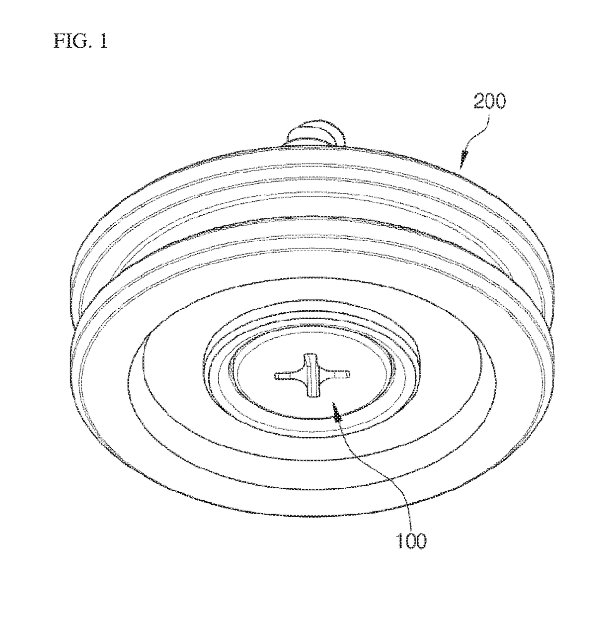
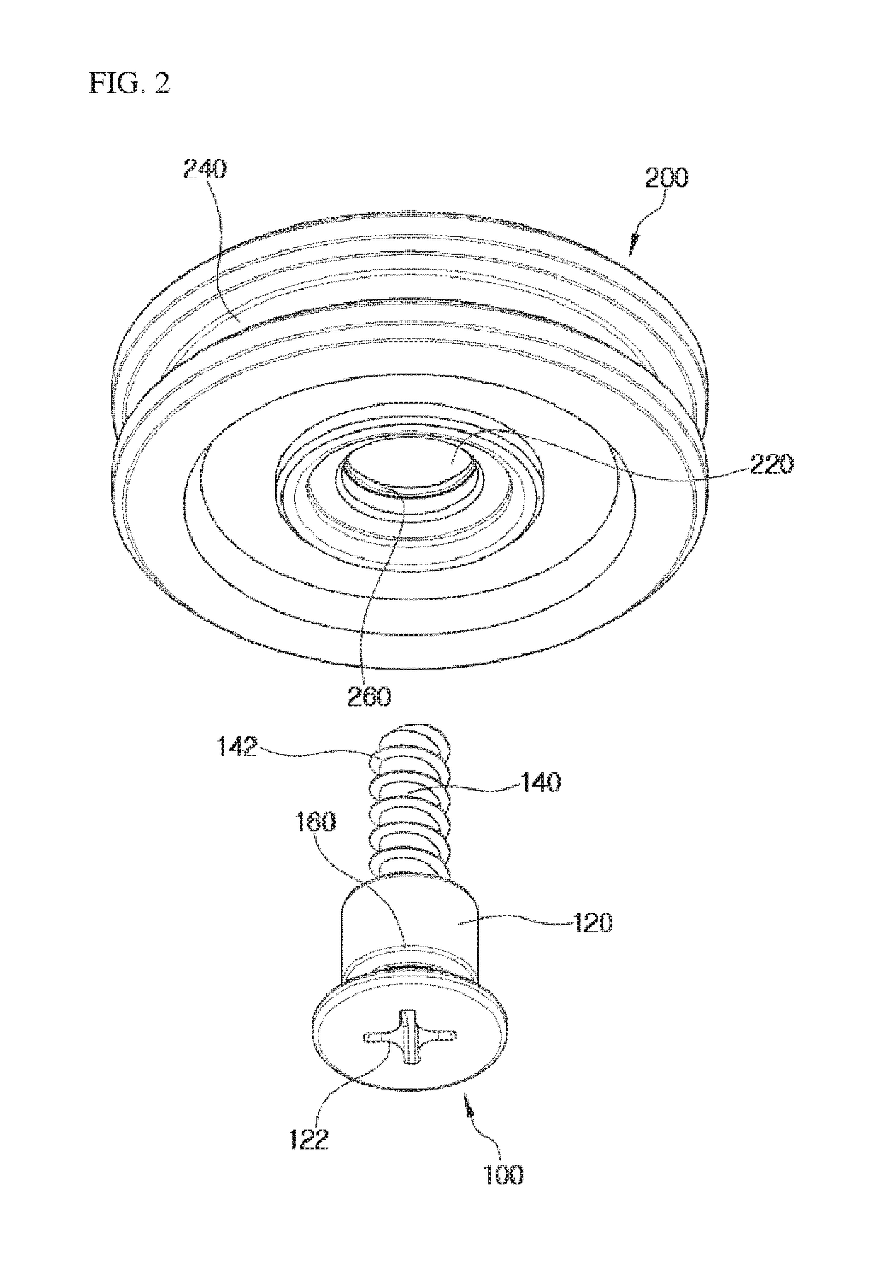
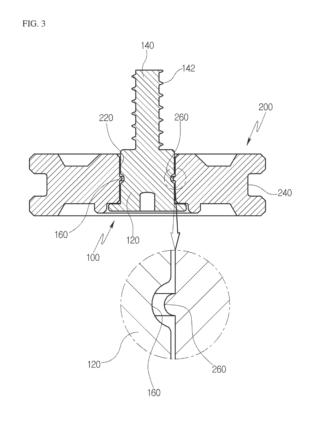
[0032]FIG. 1 is a perspective view illustrating a roller unit for a drawer according to an exemplary embodiment of the present invention, FIG. 2 is an exploded perspective view of FIG. 1, and FIG. 3 is a cross-sectional view of FIG. 1.

[0033]Referring to FIGS. 1 to 3, a roller unit for a drawer according to an exemplary embodiment of the present invention is configured to include a rotating support shaft 100 fixed to an accommodation body (not illustrated), an idle roller 200 idle-rotatably coupled to the rotating support shaft 100, and coupling structures provided at assembled portions of the rotating support shaft 100 and the idle roller 200, respectively, to more simply implement the coupling between the rotating support shaft and the idle roller 200.

[0034]The rotating support shaft 100 is fixed to the accommodation body in a screw fastening manner so that the accommodation body is installed to be slidably movable with respect to a main body, and is fixed at a plurality of po...

second exemplary embodiment

[0044

[0045]FIG. 4 is an exploded view illustrating a structure of an outer circumferential surface of a rotating support shaft and an inner circumferential surface of an idle roller to facilitate understanding, the rotating support shaft and the idle roller configuring a roller unit for a drawer according to another exemplary embodiment of the present invention, and FIG. 5 is a perspective view illustrating a rotating support shaft configuring a roller unit for a drawer according to another exemplary embodiment of the present invention.

[0046]Referring to FIGS. 4 and 5, a roller unit for a drawer according to another exemplary embodiment of the present invention includes a rotating support shaft 100 and an idle roller 200 having the same configuration as an exemplary embodiment described above. However, the roller unit for a drawer according to another exemplary embodiment of the present invention has a structure in which configuration of a coupling structure is different from that i...

third exemplary embodiment

[0058

[0059]FIG. 6 is an exploded view illustrating a structure of an outer circumferential surface of a rotating support shaft and an inner circumferential surface of an idle roller to facilitate understanding, the rotating support shaft and the idle roller configuring a roller unit for a drawer according to still another exemplary embodiment of the present invention, and FIG. 7 is a perspective view illustrating a rotating support shaft configuring a roller unit for a drawer according to still another exemplary embodiment of the present invention.

[0060]Referring to FIGS. 6 and 7, a roller unit for a drawer according to still another exemplary embodiment of the present invention includes a rotating support shaft 100, an idle roller 200, and a coupling structure having the same configuration as the exemplary embodiment of FIGS. 5 and 6. However, the roller unit for a drawer according to still another exemplary embodiment of the present invention has a structure in which configuration...


PUM


Abstract

A roller unit for a drawer capable of decreasing the number of components, improving assembly productivity, and continuously maintaining a normal assembly state of the component by changing a structure of an assembled portion of the components configuring the roller unit. The roller unit includes a rotating support shaft fixed to an accommodation body, an idle roller idle-rotatably coupled to the rotating support shaft, and coupling structures provided at assembled portions of the rotating support shaft and the idle roller, respectively, the coupling structures including a locking groove formed in a circumferential direction with respect to an outer circumferential surface of the rotating support shaft, a protrusion formed on an inner circumferential surface of a fastening hole of the idle roller and coupled to the locking groove, and an assembly guiding groove formed at one end of the outer circumferential surface of the rotating support shaft.

Description

RELATED APPLICATIONS[0001]The present invention is a U.S. National Stage under 35 USC 371 patent application, claiming priority to Ser. No. PCT / KR2016 / 006134, filed on 9 Jun. 2016; which claims priority from KR 10-2015-0118672, filed 24 Aug. 2016, and KR 10-2016-0002244, filed 7 Jan. 2016, the entirety of all of which are incorporated herein by reference.TECHNICAL FIELD[0002]Exemplary embodiments of the present invention relate to a roller unit for a drawer, and more particularly, to a roller unit for a drawer capable of decreasing the number of components, improving assembly productivity, and continuously maintaining a normal assembly state of the component by changing a structure of an assembled portion of the components configuring the roller unit.BACKGROUND ART[0003]Generally, a roller unit is a component in which a cylindrical wheel is rotatably coupled with a fastening member to change sliding friction generated at the time of sliding into rolling friction to reduce frictional...

Claims


Application Information

Patent Timeline
Patent Type & Authority Patents(United States)
IPC IPC(8): A47B88/437A47B88/487F16C29/04B60B33/00
CPCA47B88/487A47B88/437F16C29/04B60B2200/20A47B2210/175B60B33/0028
Inventor KIM, JAE WON
Owner SEGOS
Why Eureka
Try Eureka