Rotation projector

a projector and rotating technology, applied in the direction of projectors, slide projectors, instruments, etc., can solve the problems of static projection pattern of conventional projectors, visual fatigue on viewers, and lack of conventional projectors that drive the film to rota

Active Publication Date: 2018-12-04
GEMMY IND CORP
View PDF2 Cites 5 Cited by
  • Summary
  • Abstract
  • Description
  • Claims
  • Application Information

AI Technical Summary

Benefits of technology

[0005]The main objective of the invention is to provide a rotation projector that solves the problem that the static pattern projected by the conventional projector cannot be used in a cheerful occasion or party.

Problems solved by technology

However, the pattern projected by the conventional projector is static.
The conventional projector lacks a mechanism that drives the film to rotate.
The static pattern causes visual fatigue on a viewer and is unable to bring about a joyful atmosphere in a party when needed.

Method used


Image

  • Rotation projector
  • Rotation projector
  • Rotation projector

Examples


Embodiment Construction

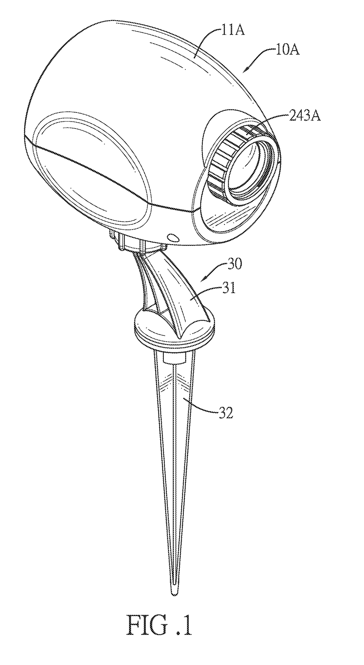
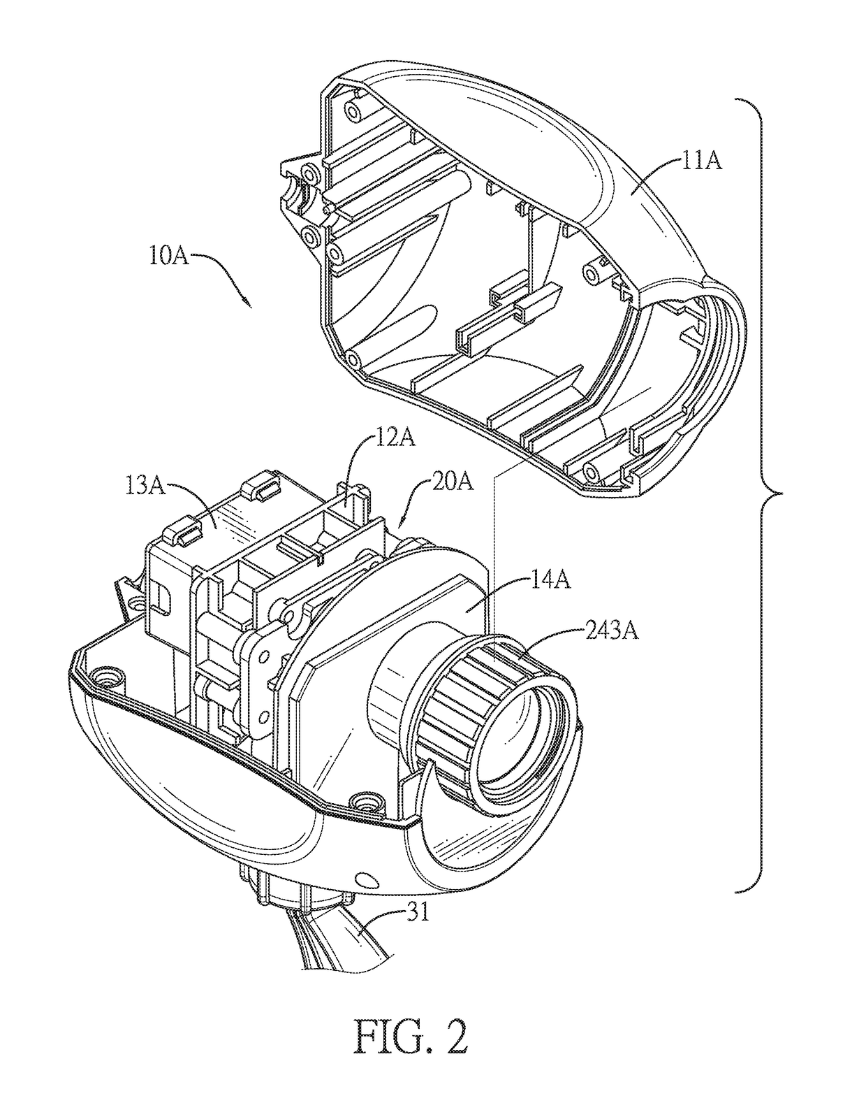
[0021]With reference to FIGS. 1, 2, 5, and 8, a rotation projector in accordance with the present invention comprises a housing 10A, 10B, 10C and a projection device 20A, 20B, 20C.

[0022]With reference to FIGS. 1, 2, 5, and 8, the housing 10A, 10B, 10C has a casing 11A, 11B, 11C, a mounting support 12A, 12B, 12C, a power supply member 13A, 13B, 13C, and a waterproof cover 14A, 14B, 14C. The casing 11A, 11B, 11C has a front surface. The mounting support 12A, 12B, 12C is disposed in the casing 11A, 11B, 11C. The power supply member 13A, 13B, 13C is disposed in the casing 11A, 11B, 11C. The waterproof cover 14A, 14B, 14C is mounted on the casing 11A, 11B, 11C.

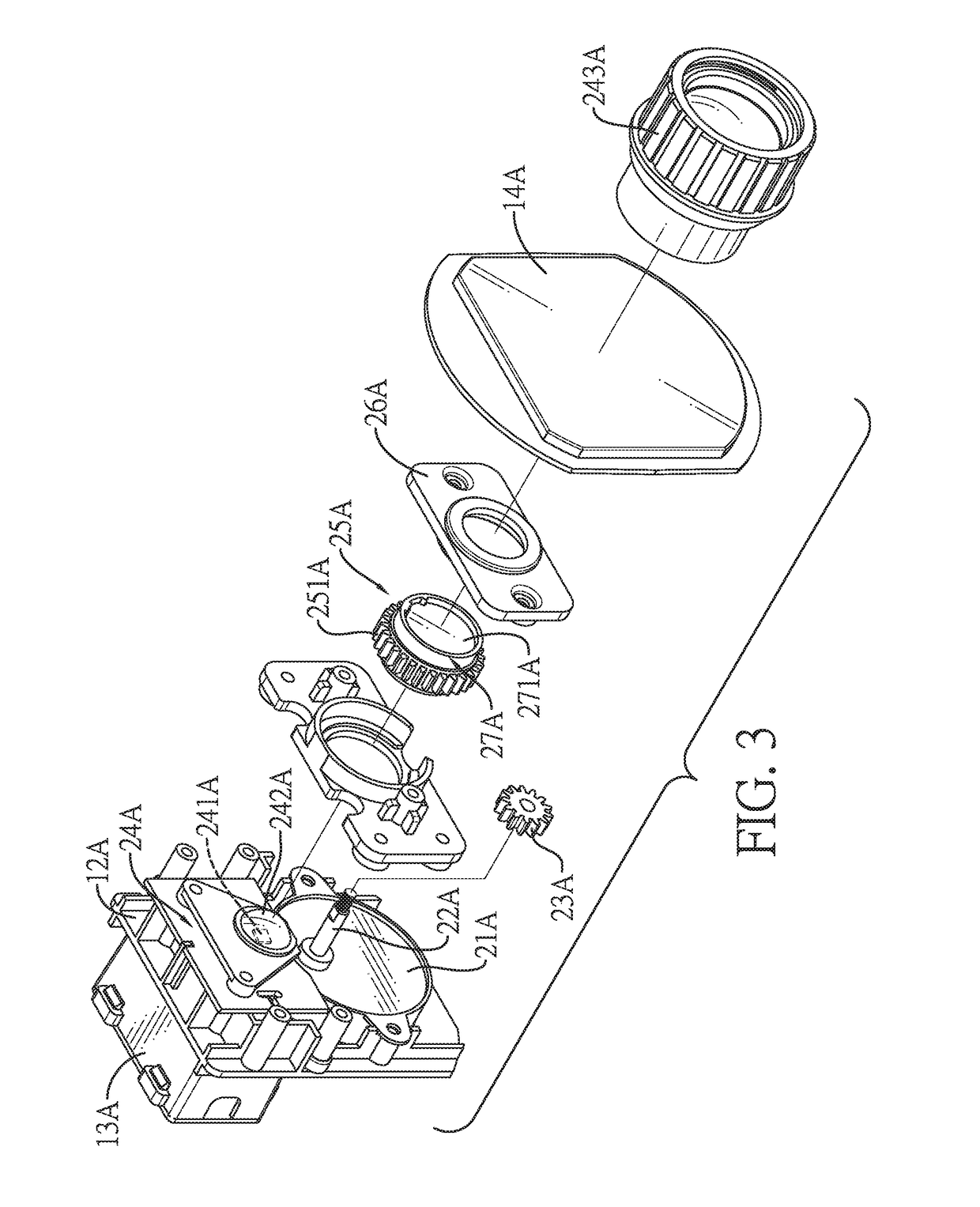
[0023]With reference to FIGS. 2, 5, and 8, the projection device 20A, 20B, 20C is mounted in the casing 11A, 11B, 11C. With further reference to FIGS. 3, 6, and 9, the projection device 20A, 20B, 20C has a driver 21A, 21B, 21C, a driving shaft 22A, 22B, 22C, a drive gear 23A, 23B, 23C, a lighting member 24A, 24B, 24C, a gear assemb...


PUM


Abstract

A rotation projector has a housing and a projection device. The housing has a casing and a mounting support. The mounting support is disposed in the casing. The projection device disposed in the casing and having a driver, a driving shaft, a drive gear, a lighting member, a gear assembly, and a film reel assembly. The driver is mounted on the mounting support. The driving shaft is driven to rotate by the driver. The drive gear is securely mounted on the driving shaft. The lighting member is mounted on the mounting support. The gear assembly is rotatably mounted on the mounting support and engages with the drive gear. The film reel assembly is mounted on the gear assembly and is disposed in front of the lighting member. A pattern projected by the projection device will be rotated.

Description

BACKGROUND OF THE INVENTION1. Field of the Invention[0001]The present invention relates to a rotation projector, and more particularly to a rotation projector that can project a rotating pattern by a rotary gear that drives a film in the rotation projector to rotate.2. Description of Related Art[0002]A conventional projector can project clear patterns. The conventional projector has a housing, a lighting member, a film, and an imaging lens. The housing has a projection opening formed through a front end of the housing. The lighting member is mounted in the housing and has a side surface facing the projection opening. The film is mounted in the housing and is disposed in front of the lighting member. The imaging lens is mounted in the projection opening and is disposed in front of the film. When the conventional projector is in use, light is emitted from the lighting member and passes through the film and the imaging lens, so as to form a clear pattern on a surface.[0003]However, the...

Claims


Application Information

Patent Timeline
Patent Type & Authority Patents(United States)
IPC IPC(8): G03B21/43G03B21/14G03B21/20
CPCG03B21/43G03B21/145G03B21/2013G03B21/208G03B21/001
Inventor ZHANG, CHENG-CHUNCHANG, LIO YENWEI
Owner GEMMY IND CORP
Why Eureka
Try Eureka