
Earphone

a technology for headphones and earphones, applied in the field of headphones, can solve the problems of deteriorating over-all frequency response, and achieve the effect of preferable frequency respons

Inactive Publication Date: 2018-12-04
AUDIO-TECHNICA
View PDF11 Cites 3 Cited by
  • Summary
  • Abstract
  • Description
  • Claims
  • Application Information

AI Technical Summary

Benefits of technology

[0023]Accordingly, one of the main objects of the present invention is to provide an earphone having a preferred frequency response by particularly suppressing attenuation of high-frequency components, in an ear phone using a plurality of specific BA driver units. Another object of the invention is to provide an earphone wearable to users' ear concha without an uncomfortable feeling, by considering a positional relationship between the BA driver units disposed in the unit case to reduce a size of the unit case 3.
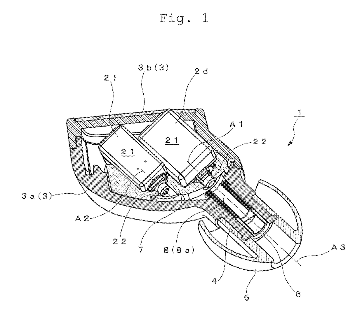
[0029]An earphone according to the present invention has a feature that the sound emission axis of the drive unit that reproduces sound waves particularly including a high-frequency range is disposed so as to pass through the opening of a sound delivery tube communicating with the unit case. This structure allows the sound waves of the high-frequency range in particular to be guided to user's ear concha as a direct sound without being affected by reflection in the unit case; an earphone achieving a comprehensively preferable frequency response can be provided.
[0030]In addition to the above configuration, by employing another configuration in which the sound outlet nozzle of the driver unit reproducing sound waves of other than high frequency range is disposed at a retracted position with respect to the sound outlet nozzle of the driver unit reproducing sound waves including a high-frequency range along the parallel sound emission axes, driver units are disposed in a unit case without requiring to enlarge the size of the unit case in which the driver units are accommodated. This makes it possible to provide an earphone that can be worn on the user's concha without feeling uncomfortable.

Problems solved by technology

In conventional canal-type earphones, the overall frequency response may be deteriorated due to overlapping of the above described factors.

Method used


Image

  • Earphone
  • Earphone
  • Earphone

Examples


Embodiment Construction

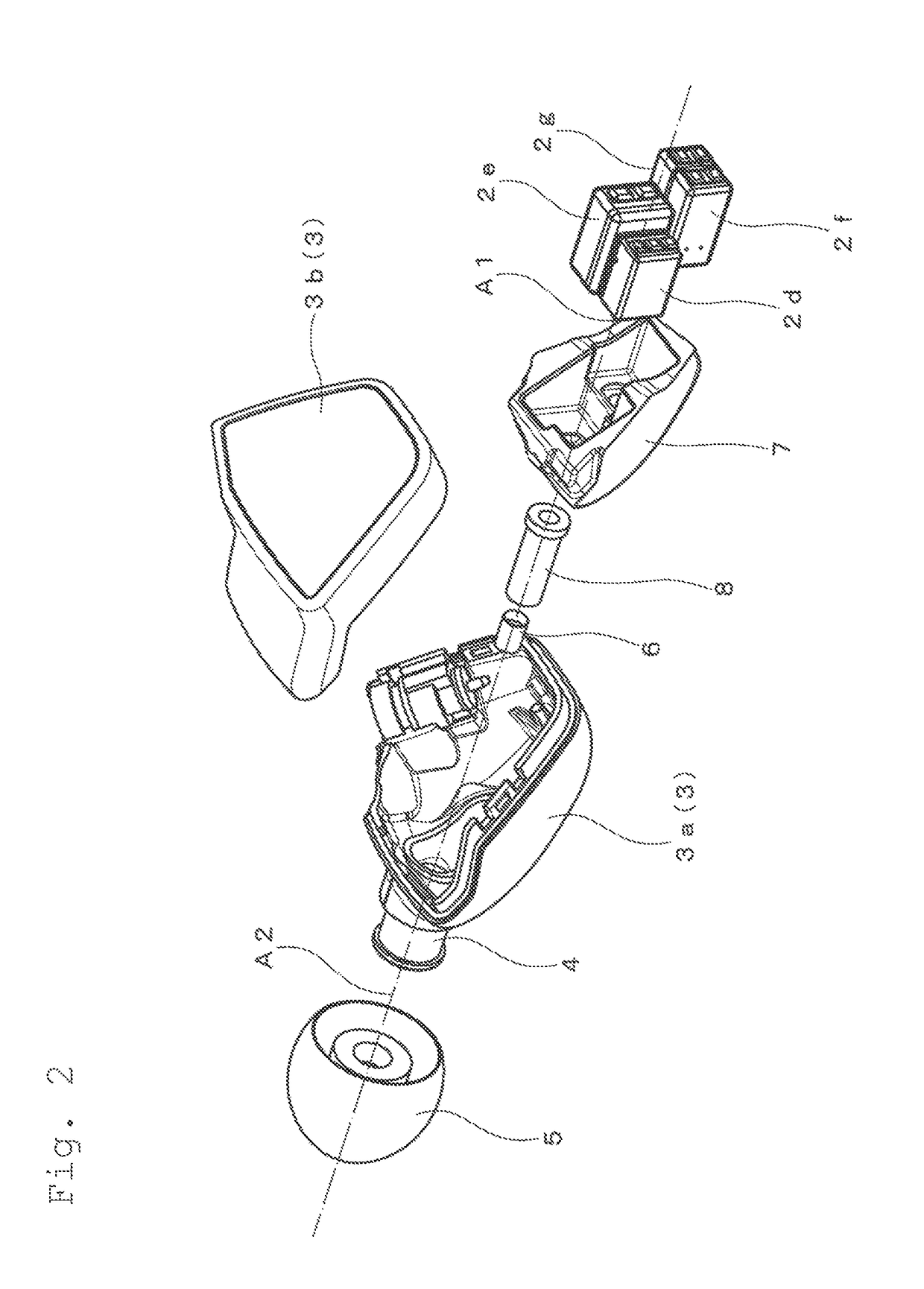
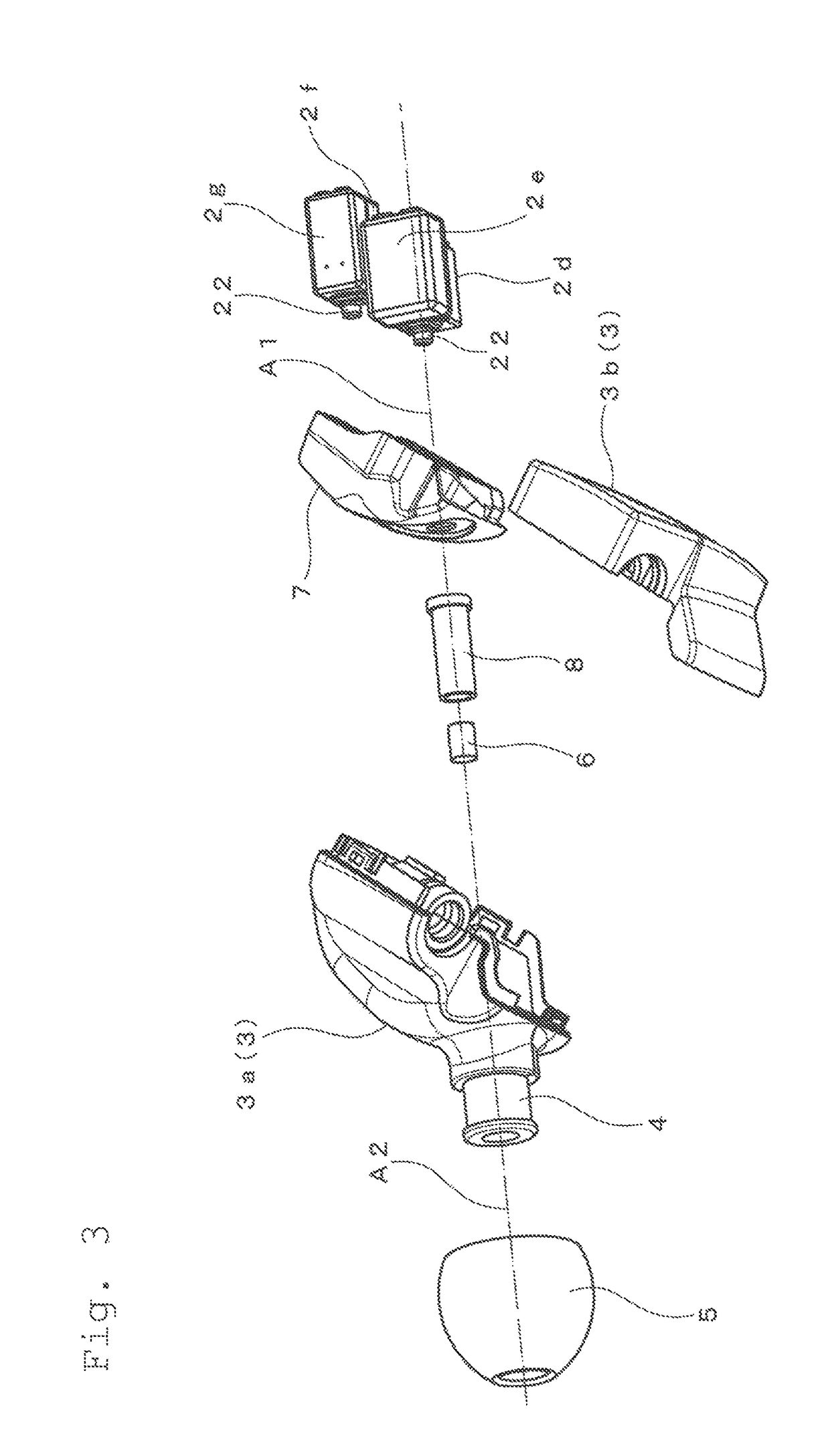
[0035]An earphone according to the present invention will be described on the basis of an embodiment with reference to drawings FIGS. 1 through 3. In the following embodiments, members, whose functions are the same as those shown in FIG. 4, are denoted by the same reference numerals.

[0036]An earphone shown in FIG. 1 is a canal type earphone. This canal type ear phone includes, as basic components, four driver units 2d to 2g, a unit case 3 that houses the driver units 2d to 2g, a sound delivery tube 4 that communicates with the unit case 3 as to lead sound waves to a user's ear canal, and an eartip attached to an outer circumferential surface of the sound delivery tube 4.

[0037]The unit case 3 is composed of a base member 3a which is a front half of the unit case and a cover 3b which is a rear half of the unit case. Further, a sound delivery tube is integrally formed in the base member 3a, and the unit case is formed by fitting the cover 3b to the base member 3a.

[0038]The unit case 3...


PUM


Abstract

An earphone includes a first driver units reproducing sound waves in a high-frequency range, a second driver units reproducing sound waves other than the high-frequency range of the first driver units, and a unit case for housing the respective driver units and a sound delivery tube for leading sound waves from the driver units to a user's ear canal, the sound delivery tube being formed to communicate with the unit case. A sound emission axis of the first driver units and a sound emission axis of the second driver units are disposed in parallel to each other, and the sound emission axis of the first driver unit passes through in an opening of the sound delivery tube. This construction, including multiple driver units for producing different frequency ranges, allows to provide an earphone in which attenuation of high-frequency components in particular is reduced.

Description

RELATED APPLICATIONS[0001]The present application is based on, and claims priority from, Japanese Application No. JP2016-149206 filed Jul. 29, 2016, the disclosure of which is hereby incorporated by reference herein in its entirety.BACKGROUND OF THE INVENTIONField of the Invention[0002]The present invention relates to in-ear headphones, such as canal headphones (ear plug type), which enable a reproduced sound from driver units to propagate faithfully.Description of the Related Art[0003]A canal earphone includes a driver unit that reproduces sound waves on receiving an audio signal, a unit case that accommodates the driver unit, a sound delivery tube that communicates with the unit case and leads a reproduced sound (sound waves) to users' ear canal, and an eartip that is provided to cover the tip end portion of the sound delivery tube.[0004]Such a canal earphone has an advantage of high isolation not affected by ambient noises, because the eartip is worn in close contact with the use...

Claims


Application Information

Patent Timeline
Patent Type & Authority Patents(United States)
IPC IPC(8): H04R25/00H04R1/28H04R1/24H04R1/10
CPCH04R1/1016H04R1/10H04R25/604H04R1/24H04R1/2857H04R1/1075H04R1/1058H04R2201/105
Inventor TSUBONE, KODAI
Owner AUDIO-TECHNICA
Learn More