
Constant current transmitting system for measurement while drilling of electromagnetic wave geosteering tool

A geosteering and measurement-while-drilling technology, which is applied in construction and other directions, can solve problems such as the downhole power generation system and current overload, and achieve the effects of high-efficiency transmission, suppressed attenuation, and good reception

Inactive Publication Date: 2014-12-17
BC P INC CHINA NAT PETROLEUM CORP +1
View PDF8 Cites 3 Cited by
  • Summary
  • Abstract
  • Description
  • Claims
  • Application Information

AI Technical Summary

Problems solved by technology

There is also a U.S. invention patent with application number 7,477,162, the name of the invention: Wireless electromagnetic telemetry system and method for bottomhole assembly, which only proposes how to launch low-frequency wireless electromagnetic waves in the formation to establish an electromagnetic channel in terms of tool structure, and does not specifically describe how to use it from From the perspective of the circuit to achieve and overcome the impact of the attenuation of electromagnetic waves on the results of ground reception under different formations and different drilling media
[0004] The existing wireless electromagnetic wave measurement while drilling tools that are commonly used only rely on the maximum natural discharge current of the battery to supply power, without considering how to avoid the current overload that may be affected by different formation resistivities when using an underground power generation system to achieve high-power power supply or super light load phenomenon

Method used


Image

  • Constant current transmitting system for measurement while drilling of electromagnetic wave geosteering tool

Examples


Embodiment 1

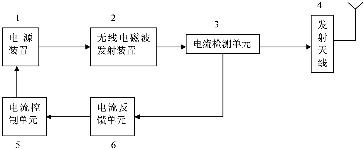
[0018] Embodiment 1: as figure 1 As shown, a constant current transmitting system for electromagnetic wave geosteering tools for measuring while drilling, the wireless electromagnetic wave transmitting device 2 is connected to the current detection unit 3, the current detection unit 3 is connected to the current signal feedback unit 6 and the transmitting antenna 4, and the current signal feedback unit 6 is connected to the current control unit 5; the current control unit 5 is connected to the power supply device 1, and the power supply device 1 is connected to the wireless electromagnetic wave transmitting device 2,

[0019] The current detection unit 3 is placed between the wireless electromagnetic wave transmitting device 2 and the transmitting antenna 4 for detecting the electromagnetic wave transmitting current;

[0020] The current signal feedback unit 6 is placed between the current detection unit 3 and the current control unit 5, and is used to feed back the magnitude ...


PUM


Abstract

The invention provides a constant current transmitting system for measurement while drilling of an electromagnetic wave geosteering tool and belongs to the field of oil exploitation or underground mine exploration or the like. A wireless electromagnetic wave transmitting device is connected with a current detecting unit, the current detecting unit is connected with a current signal feedback unit and a transmitting antenna, and the current signal feedback unit is connected with a current control unit. The current control unit is connected with a power supply device, and the power supply device is connected with the wireless electromagnetic wave transmitting device. The constant current transmitting system can be applied to measurement while drilling of the wireless electromagnetic wave geosteering tool or other working modes with wireless electromagnetic waves used for achieving data transmission between stratums or between ore beds, and working media comprise drilling fluid, clean water, air, nitrogen and the like. A power control method for wireless electromagnetic wave data transmission has the advantages that attenuation on transmission signals by the change of resistivity of stratum and drilling media is well lowered so that the wireless electromagnetic data can be better detected on the ground.

Description

technical field [0001] The invention relates to a constant current emission system for a geo-steering tool for measuring electromagnetic waves while drilling, and belongs to the fields of oil exploitation, geological and mineral exploration, and the like. Background technique [0002] In oil drilling engineering or geological exploration, in directional drilling or horizontal drilling, and underbalanced wells, it is often necessary to use wireless electromagnetic wave geosteering tools. At present, relatively mature wireless electromagnetic wave geosteering tools at home and abroad are widely used in the field. Its working principle is: a geosteering unit is placed in the drilling tool, and the tool uses the drill collar as an electrode to transmit wireless electromagnetic wave signals to the formation, which are used to send geological parameters and drill bit position and other parameters while drilling to the ground receiving equipment. Whether these products are powered...

Claims


Application Information

Patent Timeline
IPC IPC(8): E21B47/13
Inventor 张连成
Owner BC P INC CHINA NAT PETROLEUM CORP
Learn More