Photoelectric smoke sensor

a technology of photoelectric smoke sensor and optical fiber, which is applied in the direction of fire alarm, smoke/gas actuation, instruments, etc., can solve the problems of deteriorating smoke detection performance, inability to avoid the growth insufficient explosion-proof performance of the photoelectric smoke sensor, etc., to achieve sufficient tightness of the housing, improve the explosion-proof property, and achieve sufficient explosion-proof performance

Active Publication Date: 2018-12-11
FENWAL CONTROLS OF JAPAN
View PDF53 Cites 2 Cited by
  • Summary
  • Abstract
  • Description
  • Claims
  • Application Information

AI Technical Summary

Benefits of technology

[0017]An object of the present invention is to provide a photoelectric smoke sensor in which a flame accompanying an explosion does not leak to a designated explosion-proof zone even if an explosion occurs inside the housing, airtightness of the housing does not need to be ensured by using an exclusive sealant, and an explosion resulting from deterioration of the sealant can be prevented preliminarily.
[0020]The first support portion and the second support portion are configured to prevent escape of flame from the circuit accommodation chamber to the inflow chamber.
[0021]According to a preferable example of the present invention, the first support portion has a first gap communicating with the circuit accommodation chamber and the inflow chamber between the first support portion and the outer peripheral surface of the first light guide, and the second support portion has a second gap communicating with the circuit accommodation chamber and the inflow chamber between the second support portion and the outer peripheral surface of the second light guide. Each of the sizes of the first and second gaps and the lengths along the depth direction of the first and second gaps is set to a value which prevents escape of the flame from the circuit accommodation chamber to the inflow chamber.
[0023]According to the present invention, even if an explosion occurs in the circuit accommodating chamber inside the housing, the flame generated by the explosion disappears in the process of passing through the first support portion and the second support portion. For this reason, the flame accompanying the explosion can be prevented from leaking into the designated explosion-proof area or igniting combustible or explosive gas in the designated explosion-proof area, and sufficient explosion-proof performance can be obtained.
[0024]Furthermore, the tightness of the housing can be ensured sufficiently without using a sealant formed of resin. Therefore, the present invention can contribute to the improvement of the explosion-proof property and maintenance of the photoelectric smoke sensor can be executed easily.

Problems solved by technology

In the photoelectric smoke sensor using the optical fiber, however, the light emitting portion and the light receiving portion for sensing the smoke and the explosion-proof container containing the circuit board are separated from each other, and the photoelectric smoke sensor becoming larger in size cannot be avoided.
Moreover, the optical fiber made of resin has a property of attenuating the optical signal from the light emitting portion to the light receiving portion, and the performance of detecting smoke is deteriorated.
Furthermore, optical fibers made of glass are more expensive than the optical fibers formed of resin, which is a problem in terms of costs.
As a result, when the combustible gas leaks to the hazardous place, the combustible gas may enter the explosion-proof container, which is one of factors causing the explosion.

Method used


Image

  • Photoelectric smoke sensor
  • Photoelectric smoke sensor
  • Photoelectric smoke sensor

Examples


first embodiment

[0058]A First Embodiment of the present invention will be described hereinafter with reference to FIG. 1 to FIG. 13.

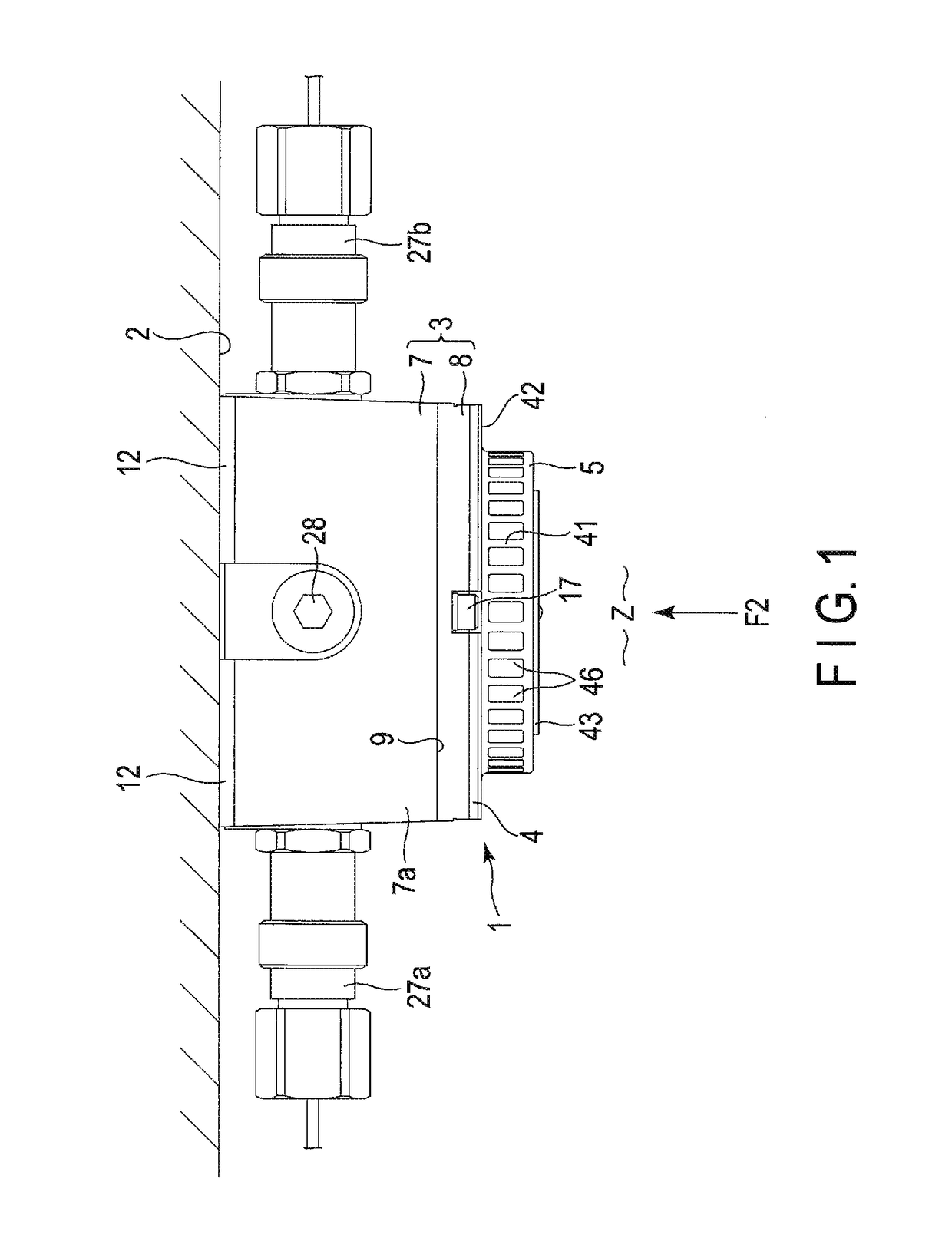
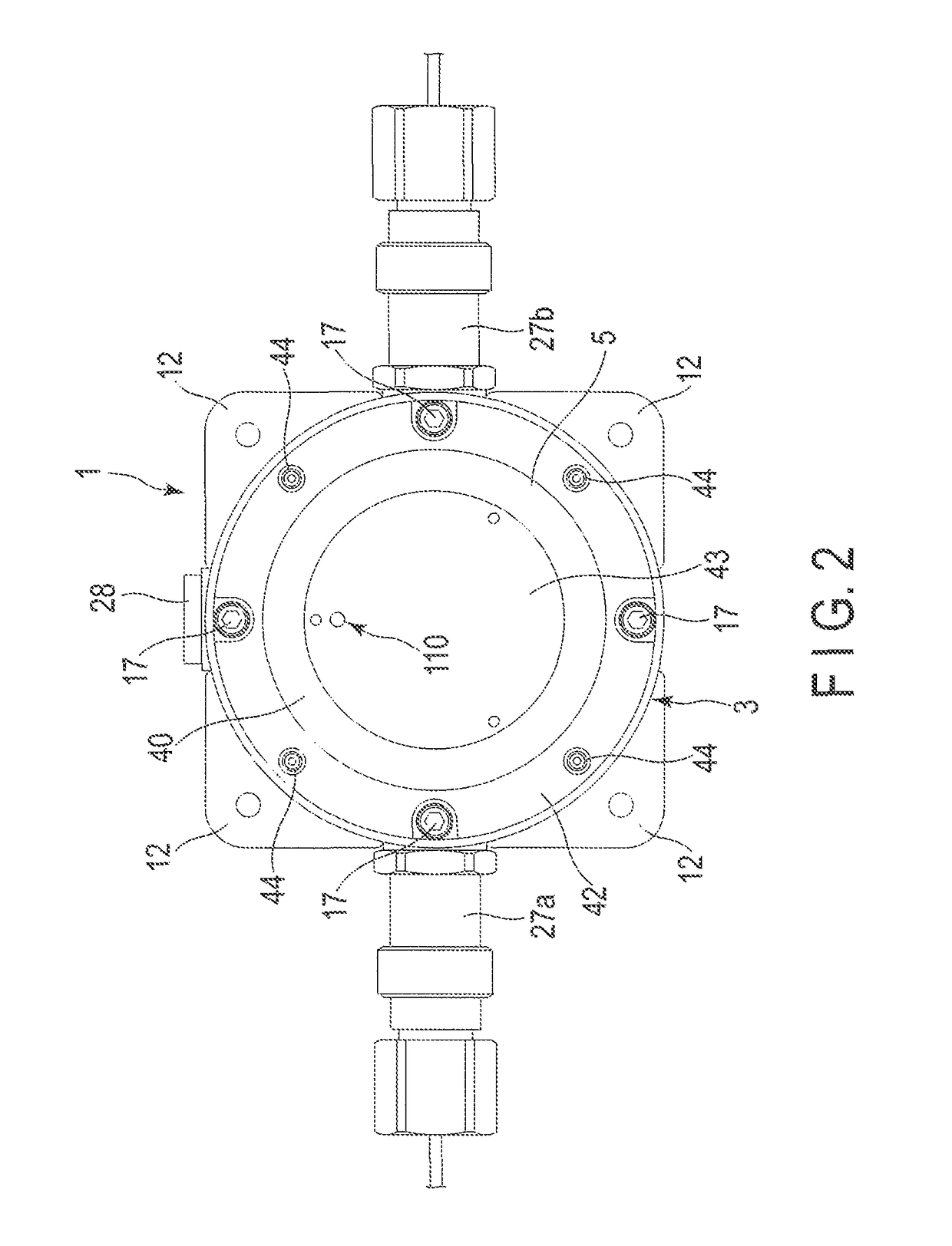
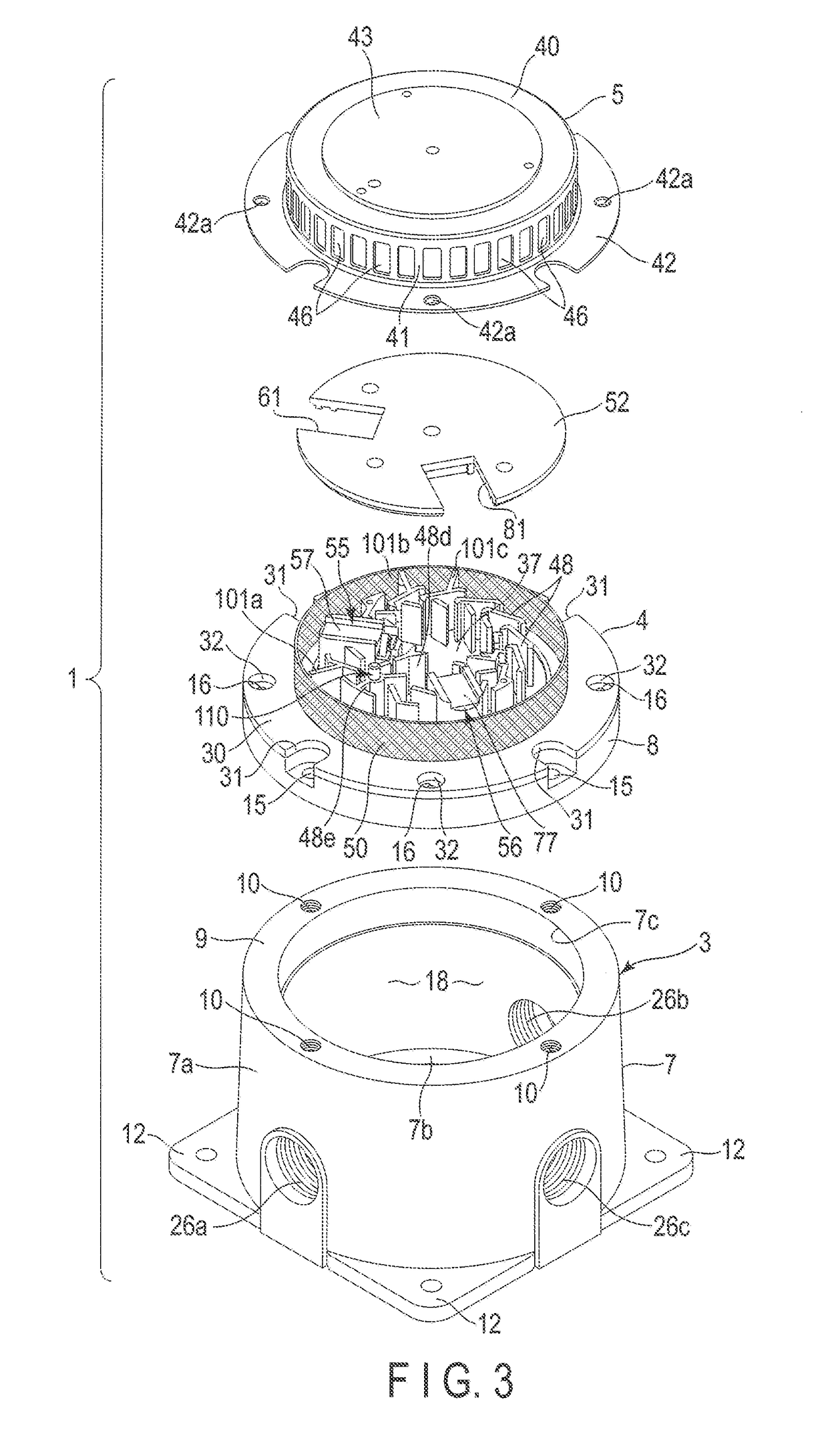
[0059]FIG. 1 shows an integrated photoelectric smoke sensor 1 installed on a ceiling surface 2 of a building. The photoelectric smoke sensor 1 is exposed in a designated explosion-proof area Z in the building. As shown in FIG. 1 to FIG. 3, the photoelectric smoke sensor 1 comprises a housing 3, a chamber base 4, and a protective cover 5 as main elements.

[0060]The housing 3 is formed of, for example, a metal material such as an aluminum alloy. The housing 3 is divided into a main body base 7 and a main body cover 8. As shown in FIG. 3 to FIG. 5, the main body base 7 includes a cylindrical portion 7a and a bottom wall 7b which closes an end of the cylindrical portion 7a. The cylindrical portion 7a has an annular tip surface 9 positioned on a side opposite to the bottom wall 7b. The tip surface 9 is a flat surface orthogonal to axis O1 of the housing 3 passing through the...

second embodiment

[0203]FIG. 19 discloses a Second Embodiment. In the Second Embodiment, elements corresponding to the first to third guide walls 101a, 101b, and 101c of the First Embodiment are excluded from an outer peripheral portion of a labyrinth substrate 30. The basic configuration of the photoelectric smoke sensor 1 other than those is the same as that of the First Embodiment. For this reason, in the Second Embodiment, the same constituent portions as those in the First Embodiment are denoted by the same reference numerals and their explanations are omitted.

[0204]According to the Second Embodiment, a ventilation passage 51 positioned between a plurality of shielding walls 48 and an insect screen 50 maintains an annular shape continuous in a circumferential direction of a ventilation chamber 45. In other words, since the annular insect screen 50 is distant from the shielding walls 48, air flowing from the ventilation ports 46 of the protective cover 5 can easily pass through the insect screen ...

third embodiment

[0207]FIG. 20 to FIG. 22 disclose a Third Embodiment. FIG. 20 shows a state in which a separation type photoelectric smoke sensor 200 is installed on a ceiling surface 201 of a building. The photoelectric smoke sensor 200 comprises a light emitting unit 202 and a light receiving unit 203 which are independent of each other. Each of the light emitting unit 202 and the light receiving unit 203 is an example of an optical unit. The light emitting unit 202 and the light receiving unit 203 are exposed in a designated explosion-proof zone Z in the building and face each other while spaced apart.

[0208]As shown in FIG. 20, the light emitting unit 202 comprises a protective member204, a housing 205, and a light emitting portion 206 as main elements. The protective member 204 is, for example, a rectangular box-shaped element and comprises a front plate 208 having a light irradiation hole 207 opened, a bottom plate 210 having a through hole 209 opened, and a top plate 211 directly attached to ...


PUM

PropertyMeasurementUnit
pressureaaaaaaaaaa
sizeaaaaaaaaaa
sizeaaaaaaaaaa

Abstract

A photoelectric smoke sensor includes a housing having a circuit accommodation chamber, an inflow chamber provided in the housing, a light emitting portion provided in the inflow chamber, and a light receiving portion provided in the inflow chamber. The light emitting portion includes a first light and a first support portion surrounding the first light guide. The light receiving portion includes a second light guide and guiding the light to the light receiving element and a second support portion surrounding the second light guide. The first support portion and the second support portion are configured to prevent escape of a flame from the circuit accommodation chamber to the inflow chamber.

Description

CROSS-REFERENCE TO RELATED APPLICATIONS[0001]This application is a Continuation Application of PCT Application No. PCT / JP2016 / 063244, filed Apr. 27, 2016 and based upon and claiming the benefit of priority from prior Japanese Patent Application No. 2015-165757, filed Aug. 25, 2015, the entire contents of all of which are incorporated herein by reference.BACKGROUND OF THE INVENTION[0002]1. Field of the Invention[0003]The present invention relates to a photoelectric smoke sensor installed in a hazardous place including a risk of ignition or explosion and having an explosion-proof structure.[0004]2. Description of the Related Art[0005]Smoke sensors have an advantage of being able to detect the occurrence of fire early. A photoelectric smoke sensor, which is a type of the smoke sensors, comprises a light emitting portion and a light receiving portion in a region where air enters and exits, and the region is shielded from external light by a plurality of shielding walls. When smoke accom...

Claims


Application Information

Patent Timeline
Patent Type & Authority Patents(United States)
IPC IPC(8): G01N21/53G08B17/10G08B17/107
CPCG01N21/53G08B17/107G08B17/10G01N2201/0227
Inventor IGUCHI, MASAOSHIBUYA, TADAYUKINUMAO, KANJIMASUMOTO, SHINTARO
Owner FENWAL CONTROLS OF JAPAN
Why Eureka
Try Eureka