
Subsea cable installation unit

a technology for installing units and subsea cables, which is applied in the direction of pipe laying and repair, instruments, mechanical equipment, etc., can solve the problems of cable damage, possible tangle of cables with rov umbilicals or other vertical elements, and high risk of sea bottom, so as to reduce the risk of flexible body damage due to movement of flexible bodies and entanglement, and avoid loss of control of flexible body position. , the effect of reducing the uncertainty of the position and conditions

Active Publication Date: 2018-12-11
OPTOPLAN
View PDF26 Cites 2 Cited by
  • Summary
  • Abstract
  • Description
  • Claims
  • Application Information

AI Technical Summary

Benefits of technology

The invention is a cable installation device that improves the reliability and efficiency of installing flexible cables from a vessel to a subsea location. It also includes a method for safely and securely installing subsea cables on the seabed using the device. Additionally, some embodiments of the invention provide a reliable and efficient technique for trenching cables with or without sensor stations.

Problems solved by technology

The dynamic behaviour or the cable at the sea bottom represents a high risk of cable damage.
A further risk is associated with a possible tangle of the cable with the ROV umbilical or other vertical elements, particularly if operated from the same vessel.
A GW umbilical is strong and drag displacements are limited due to the weight of the wire and the GW itself.
The limitation of such a solution is that the cable is trapped to the installation tool all the way from top to bottom.
Discontinuities such as a sensor station on a seismic cable may be expected to represent a problem when passing the rings.
A limitation of a high tension in the cable is that the touchdown point (TDP) will typically be far behind the GW, making it more complicated to observe the TDP, and the GW will be pulled backwards with respect to the vessel.
Although the prior art presents significant progress in the area of installing cables on the seabed, there are still limitations, in particular related to installation in deep waters with strong sea currents and rough seas.

Method used


Image

  • Subsea cable installation unit
  • Subsea cable installation unit
  • Subsea cable installation unit

Examples


Embodiment Construction

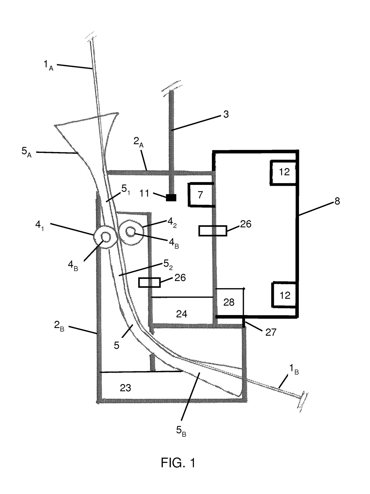
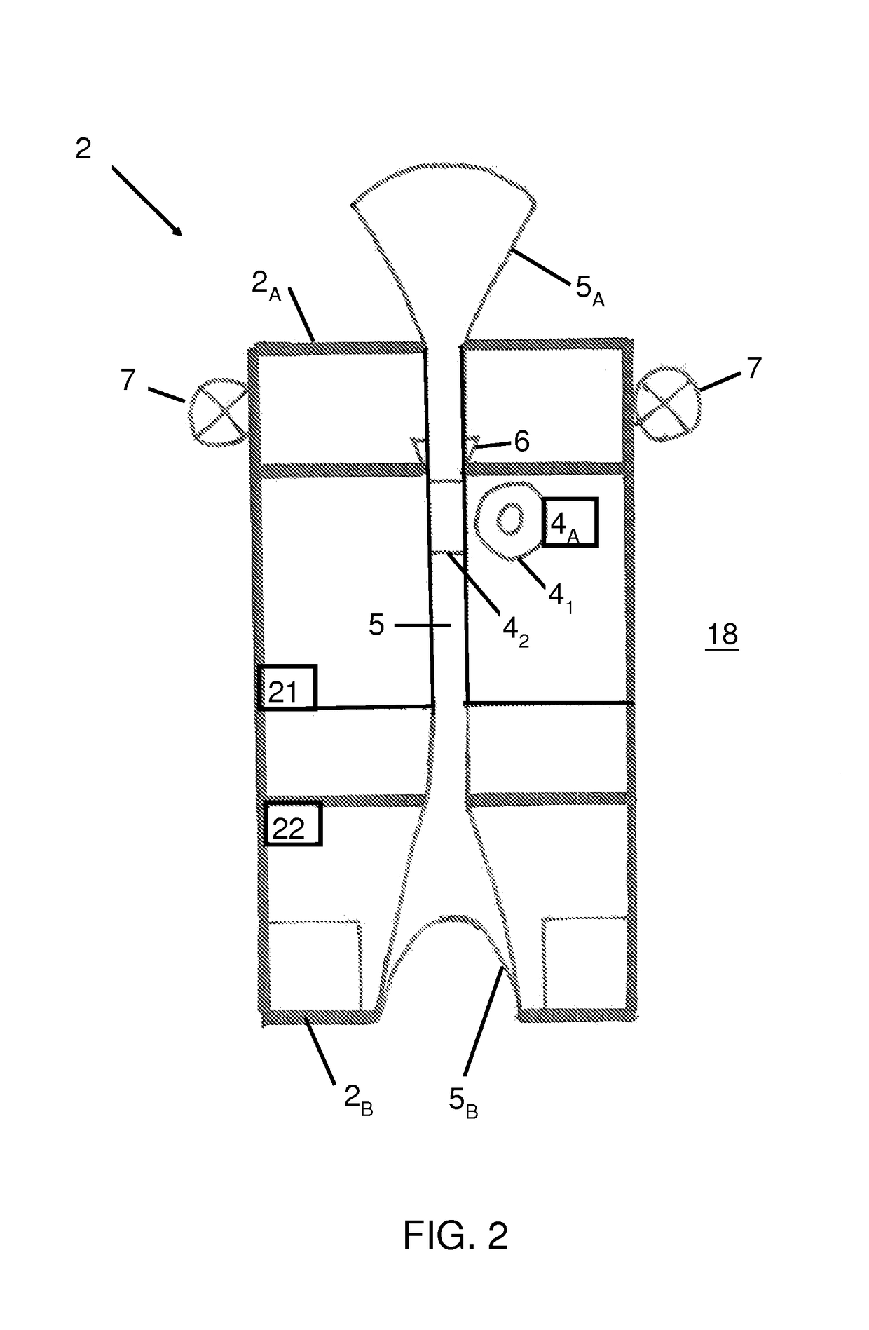
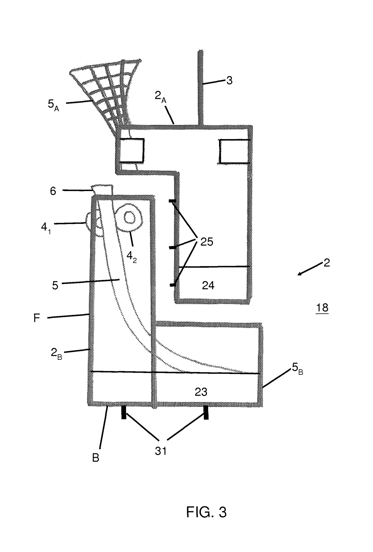
[0047]FIG. 1 illustrates schematically the installation tool of the invention that enables a pulldown of the flexible body to be installed. The flexible body 1A,B, such as for example a subsea fibre optic cable is coupled, for example by clamping, to an installation tool and controlled by a tensioner 41-2,A-B in the tool. The flexible body 1A,B is to be installed on the seabed 17 from a surface vessel 16 as indicated on FIG. 4. The installation tool is suspended from the vessel 16 using an umbilical 3. The installation tool initially has a weight sufficient to create a significant tension in the umbilical 3. The weight of the installation tool is mainly formed by a main body 2 possibly with additional loads 23, 24. By pulling down the cable 1A,B the tension in an upper part of the cable increases, thus making the upper section 1A of the cable more resistant towards shifts in position due to drag effects caused by (varying) sea currents, tidal effects, etc.

[0048]The tensioner 41-2,A-...


PUM


Abstract

A subsea installation tool for installing a flexible body, e.g. a subsea fiber cable on a seabed from a surface vessel, and an associated method for installing the flexible body on the seabed is provided. The installation tool includes a tensioner that may be coupled to the flexible body to actively pull it down, thus increasing tension in an upper section of the cable from the installation vessel to the installation tool. High tension in the upper part of the cable gives good control even in strong sea currents. At the same time the tensioner enables lower tension in the bottom part cable from the installation tool to the seabed, giving good control of the touchdown position on the seabed.

Description

CROSS-REFERENCE TO RELATED APPLICATIONS[0001]This application is a claims priority from European Patent Application No. 11162552.1, filed Apr. 15, 2011, which is hereby incorporated herein in its entirety.FIELD OF THE INVENTION[0002]The present invention relates to devices and methods for placing an elongate object such as a cable at the ocean bottom. More particularly, the present invention is related to the deployment of an ocean bottom seismic cable from a surface vessel and to the ocean bottom. Even more particularly the present invention is related the deployment of ocean bottom cables at large sea depths.BACKGROUND OF THE INVENTION[0003]Norwegian Patent No. 176686 describes devices for installing sea cables or other elongated objects at the bottom of the sea from a cable ship. It is in particular described how the geographical coordinates for the touchdown point (TDP) may be determined for a cable during its installation using a touchdown point follower which comprises navigat...

Claims


Application Information

Patent Timeline
Patent Type & Authority Patents(United States)
IPC IPC(8): H02G1/10G02B6/50H02G9/02
CPCH02G1/10H02G9/02G02B6/506
Inventor BERG, ARNE
Owner OPTOPLAN
Learn More