Boom and dipper handle assembly for an industrial machine

a technology for industrial machines and handle assemblies, which is applied in the direction of cranes, lifting devices, constructions, etc., can solve the problems of reducing the maneuverability increasing the payload of the shovel, and affecting the operation of the dipper and the handl

Active Publication Date: 2018-12-18
JOY GLOBAL SURFACE MINING INC
View PDF13 Cites 3 Cited by
  • Summary
  • Abstract
  • Description
  • Claims
  • Application Information

AI Technical Summary

Problems solved by technology

Due to the current configuration and position of the boom and the handle of electric rope shovels, shovel operators generally have difficulties maneuvering the dipper and the dipper handle in the tuck back region of the shovel.
Newer shovels also have an increased payload and a larger dipper that reduces the maneuverability of the dipper and the handle even further.
Due to the payload increase, truck bed heights have also increased, making it harder for the shovel operator to accurately unload the dipper.
Increasing the payload, the bail pull, and the reach of a shovel is detrimental to the shovel as it leads to a higher tipping moment range and a higher machine weight because of the necessary counterweight added to the shovel and increased required strength of the structures.
This increases the swing inertia (i.e., cycle time), the front idler loading, and the rocking of the shovel that can lead to a lower structural life.

Method used


Image

  • Boom and dipper handle assembly for an industrial machine
  • Boom and dipper handle assembly for an industrial machine
  • Boom and dipper handle assembly for an industrial machine

Examples


Embodiment Construction

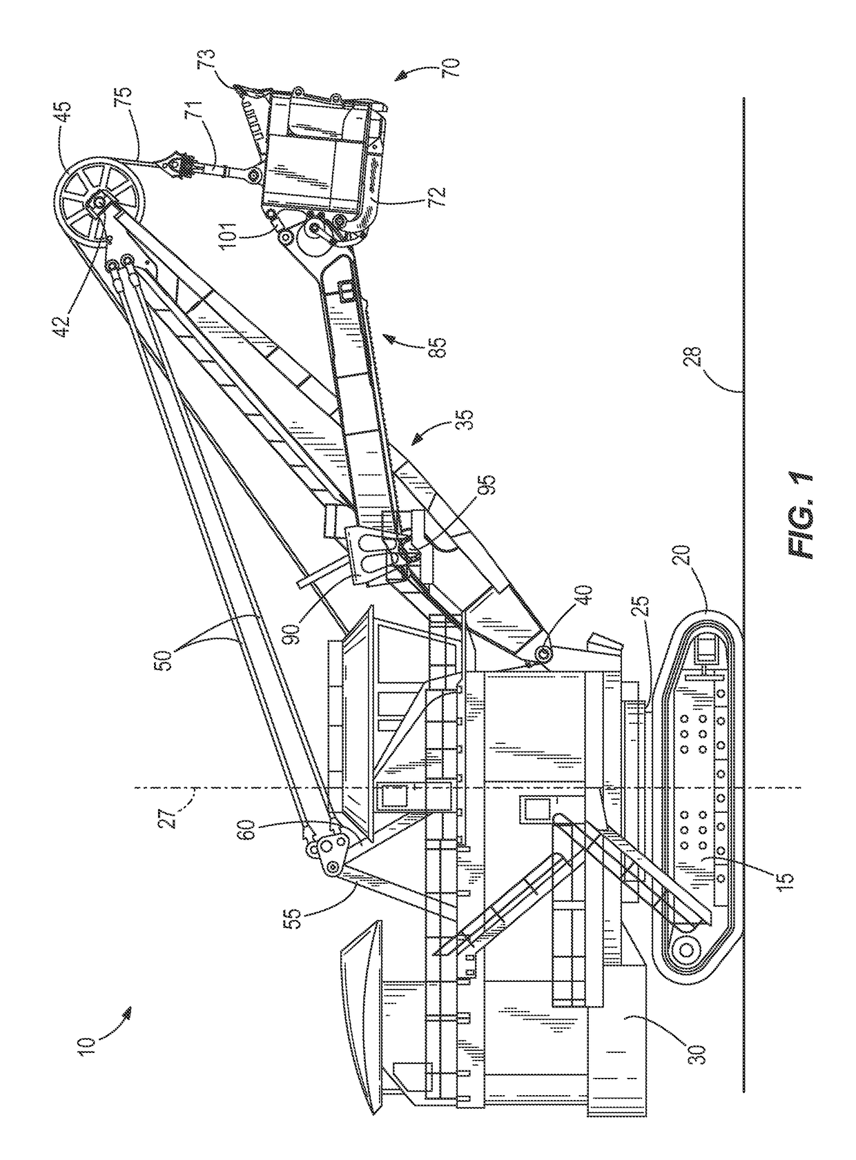
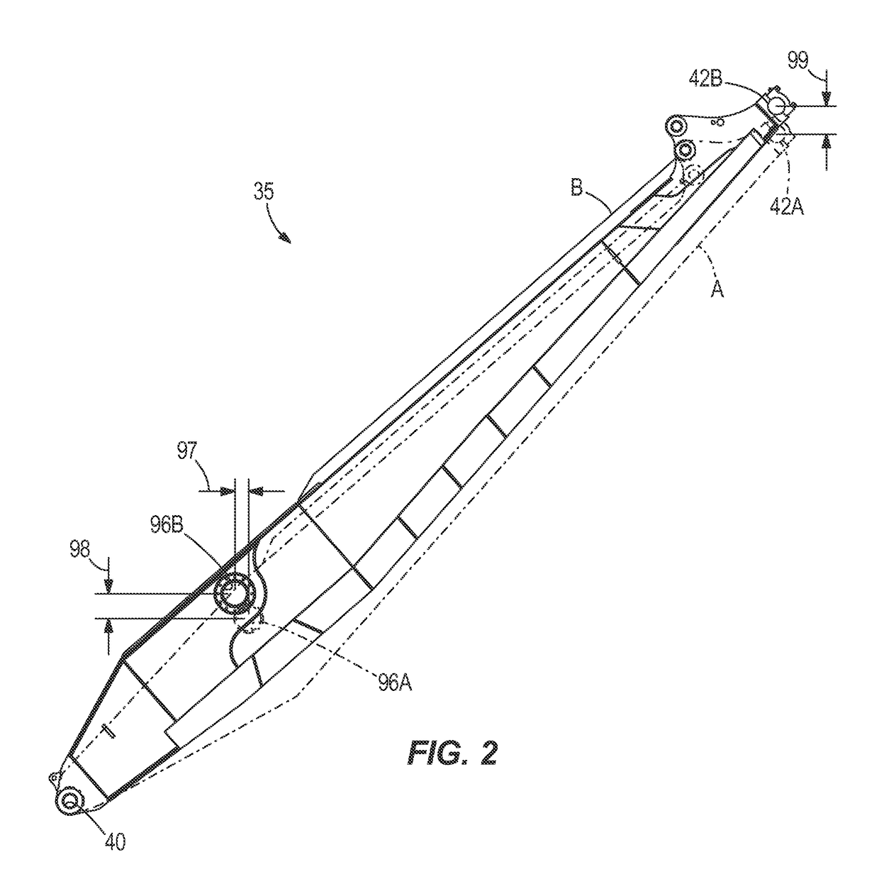
[0022]Although the invention described herein can be applied to, performed by, or used in conjunction with a variety of industrial machines, embodiments of the invention described herein are described with respect to an electric rope or power shovel, such as the power shovel 10 shown in FIG. 1. The shovel 10 includes a mobile base 15, a drive mechanism or tracks 20, a turntable 25, a revolving frame 30, a boom 35, a lower end 40 of the boom 35 (also called a boom foot), an upper end 42 of the boom 35 (also called boom point), tension cables 50, a gantry tension member 55, a gantry compression member 60, a dipper 70 having a door 72 and teeth 73, one or more hoist ropes 75, a winch drum (not shown), a dipper arm or handle 85, a saddle block 90, a shipper shaft 95 positioned in a shipper shaft aperture 96 (shown in FIG. 2), and a transmission unit (also called a crowd drive, not shown). The rotational structure 25 allows rotation of the upper frame 30 relative to the lower base 15. Th...


PUM


Abstract

A mining machine includes a base, a boom, a member, and a dipper. The base includes a frame portion that is rotatable relative to the support surface about a machine axis. The boom includes a first end coupled to the base, a second end opposite the first end, and a sheave coupled to the second end of the boom. A first distance is defined between the machine axis and the second end of the boom. The member is movably coupled to the boom about a pivot point that is positioned substantially between the first end and the second end of the boom. A second distance is defined between the machine axis and the pivot point. A ratio of the second distance to the first distance is between 27% and 43%. The dipper is coupled to an end of the member and is supported by a hoist rope.

Description

CROSS-REFERENCE TO RELATED APPLICATIONS[0001]This application claims the benefit of U.S. Provisional Patent Application No. 61 / 619,361, filed Apr. 2, 2012, the entire contents of which are incorporated herein by reference.BACKGROUND OF THE INVENTION[0002]The present invention relates to a boom and a dipper handle for an industrial machine, such as an electric rope or power shovel.[0003]In the mining field, and in other fields in which large volumes of material must be collected and removed from a work site, it is typical to employ industrial machines including a large dipper for shoveling the materials from the work site. Industrial machines, such as electric rope or power shovels, draglines, etc., are used to execute digging operations to remove material from, for example, a bank of a mine. Electric rope shovels typically include a shovel boom, a handle movably coupled to the boom and supporting the dipper, and a pulley or boom sheave rotatably supported on the boom. The handle sup...

Claims


Application Information

Patent Timeline
Patent Type & Authority Patents(United States)
IPC IPC(8): E02F3/30E02F3/38E02F3/46E02F9/14
CPCE02F3/304E02F9/14E02F3/46E02F3/38
Inventor HREN, WILLIAM
Owner JOY GLOBAL SURFACE MINING INC
Why Eureka
Try Eureka