Antistatic shoe

a technology of anti-static shoe and insole, which is applied in the field of footwear, can solve the problems of invalidating the anti-static performance of the shoe, the inability of the shoe and its insole to be stable in use and manufacturing, and the inability to meet the needs of use, so as to eliminate the risk of short circuit or

Inactive Publication Date: 2018-12-25
NEW PROCESS CORK
View PDF4 Cites 0 Cited by
  • Summary
  • Abstract
  • Description
  • Claims
  • Application Information

AI Technical Summary

Benefits of technology

[0004]Hence, it is the objective of the present invention to provide an antistatic shoe that improves the existing antistatic shoes in terms of stability and other defects.
[0014]The antistatic shoe and its insole according to the present invention are structurally firm. When the shoe is in use, or when the insole is trodden, since the second conducting member and the third conducting member are combined with the SMD resistor flatly, the SMD resistor in the antistatic unit is well based while being firmly sewn to the insole, the SMD resistor is prevented from moving under external force. This eliminates the risk of a short circuit or a broken circuit, which invalids the shoe's antistatic performance. Also, it eliminates the risk of a transient electrostatic discharge that may disadvantageously damage adjacent electronic devices or generate sparks.

Problems solved by technology

However, the configuration is disadvantageous because when the upper and lower conducting sheets are adhered or sewn to each other, the SMD resistor is not securely positioned, so the conventional antistatic shoe and its insole are not stable in terms of use and manufacturing.
Particularly, after repeated tread, it is likely the SMD resistor moves and accidently makes a short circuit or a broken circuit, which invalids the shoe's antistatic performance.

Method used


Image

  • Antistatic shoe
  • Antistatic shoe
  • Antistatic shoe

Examples


Embodiment Construction

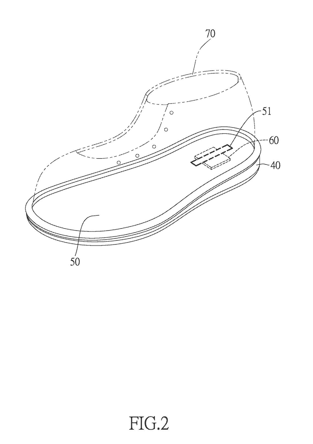
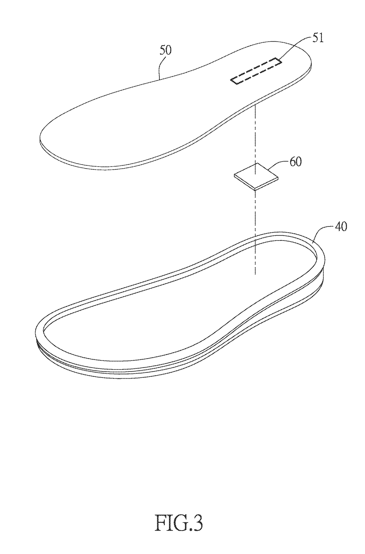
[0022]The present invention provides an antistatic shoe, as shown in FIG. 2 through FIG. 7. It comprises an outsole 40, an upper 70 connected to the outsole 40, an insole 50 placed in the upper 70 and an antistatic unit 60.

[0023]The outsole 40 has a conducting portion. In the present embodiment, the outsole 40 is made of a conducting material, so the entire outsole 40 acts as the conducting portion.

[0024]The insole 50 has a conducting portion 51. In the present embodiment, the insole 50 has its conducting portion 51 located at the bottom or the front end of the insole 50.

[0025]The antistatic unit 60 is sewn to the conducting portion 51 of the insole 50 from below and located between the outsole 40 and the insole 50.

[0026]The antistatic unit 60 includes a first base 61, which is made of a nonconducting material and has a first surface 611 and a second surface 612.

[0027]The antistatic unit 60 includes a second base 62, which is made of a nonconducting material and has a first surface ...


PUM


Abstract

An antistatic shoe includes an outsole having a conducting portion that is made of a conducting material and an insole that has a conducting portion mad of a conducting material. An antistatic unit is sewn to the conducting portion of the insole from below so as to be located between the outsole and the insole. An upper is mounted on the outsole and the insole. Electric connection between the components allows static electricity from a human body to be transmitted to a resistor in the antistatic unit, so that static electricity that would otherwise accumulate in the human body can be stably removed by the resistor and sent to the ground. This eliminates the risk of a transient electrostatic discharge that may disadvantageously damage adjacent electronic devices or generate sparks.

Description

BACKGROUND OF THE INVENTION1. Technical Field[0001]The present invention relates to footwear and more particularly to an antistatic shoe.2. Description of Related Art[0002]Referring to FIG. 1, a conventional antistatic shoe as disclosed in Taiwan Utility Model Patent No. M361917 comprises an outsole 10, which may be made of a conducting material and on which a first conducting sheet 11 is provided so that the first conducting sheet 11 exposed at the upper side of the outsole 10; and a pad 20, which has its lower side placed on the upper side of the outsole 10 and includes a body, a lining, an SMD resistor 21 (wherein “SMD” refers to a surface-mount device), an upper conducting sheet and a lower conducting sheet, wherein the body has a through hole, and the lining is placed below the body. The lining has a receiving hole that is aligned with the through hole of the body. The SMD resistor 21 is received in the through hole and the receiving hole. The SMD resistor 21 includes an envelo...

Claims


Application Information

Patent Timeline
Patent Type & Authority Patents(United States)
IPC IPC(8): A43B7/36A43B13/12A43B3/00A43B7/32
CPCA43B7/36A43B3/0005A43B13/125Y10S57/901A43B7/32A43B13/12A43B3/34
Inventor WANG, SAN-HUAIWANG, TZU-YANG
Owner NEW PROCESS CORK
Why Eureka
Try Eureka