Negative photoresist composition for KrF laser for forming semiconductor patterns

a technology of negative photoresist and semiconductor pattern, which is applied in the direction of photomechanical treatment, photosensitive materials for photomechanical apparatuses, instruments, etc., can solve the problems of unsatisfactory development of next-generation arf photoresists, inability to form desired shapes, and deterioration of profile, etc., to achieve excellent profile, high transparency, and high resolution

Active Publication Date: 2018-12-25
YCCHEM CO LTD
View PDF22 Cites 2 Cited by
  • Summary
  • Abstract
  • Description
  • Claims
  • Application Information

AI Technical Summary

Benefits of technology

[0025]According to the present invention, a negative photoresist composition for a KrF laser enables the formation of a pattern having high transparency, high resolution and an excellent profile, even in the presence of an exposure source having a short wavelength compared to a conventional negative photoresist, and is thus suitable for use in semiconductor processing.BEST MODE
[0026]Unless otherwise defined, all the technical and scientific terms used herein have the same meanings as those typically understood by those skilled in the art to which the present invention belongs. Generally, the nomenclature used herein is well known in the art and is typical.
[0027]As used herein, when any part “includes” any element, this does not mean that other elements are excluded, and such other elements may be further included unless otherwise specifically mentioned.
[0028]As used herein, the term “photoresist” refers to a mixture comprising a polymer and a photosensitive agent, the chemical properties of which change upon radiation of light thereto, thus altering the solubility thereof in a predetermined solvent when exposed to light of any wavelength, and thus, an undissolved portion is left behind to thus form a pattern after the duration of the dissolution time due to the difference in dissolution rate between an exposed portion and an unexposed portion for the solvent.
[0029]As used herein, the term “photolithography” means that, when a mask having a semiconductor circuit design is disposed between a light source and a photoresist layer applied on a silicon wafer and the light source is turned on, the circuit of the mask is transferred onto the photoresist using the properties of the photoresist.
[0030]As used herein, the term “KrF laser” refers to a krypton fluoride (KrF) laser having a wavelength of 248 nm.

Problems solved by technology

However, a negative photoresist obtained using the above composition is problematic in that the photosensitive agent therein is unable to generate a sufficient amount of acid (H+), making it impossible to form a desired shape, and also in that a profile deteriorates upon the formation of a finer pattern.
This is because the development of next-generation ArF photoresists is still unsatisfactory and also because the use of a KrF photoresist may greatly reduce the cost for mass production of semiconductors.

Method used


Image

  • Negative photoresist composition for KrF laser for forming semiconductor patterns
  • Negative photoresist composition for KrF laser for forming semiconductor patterns
  • Negative photoresist composition for KrF laser for forming semiconductor patterns

Examples


substitution example 1

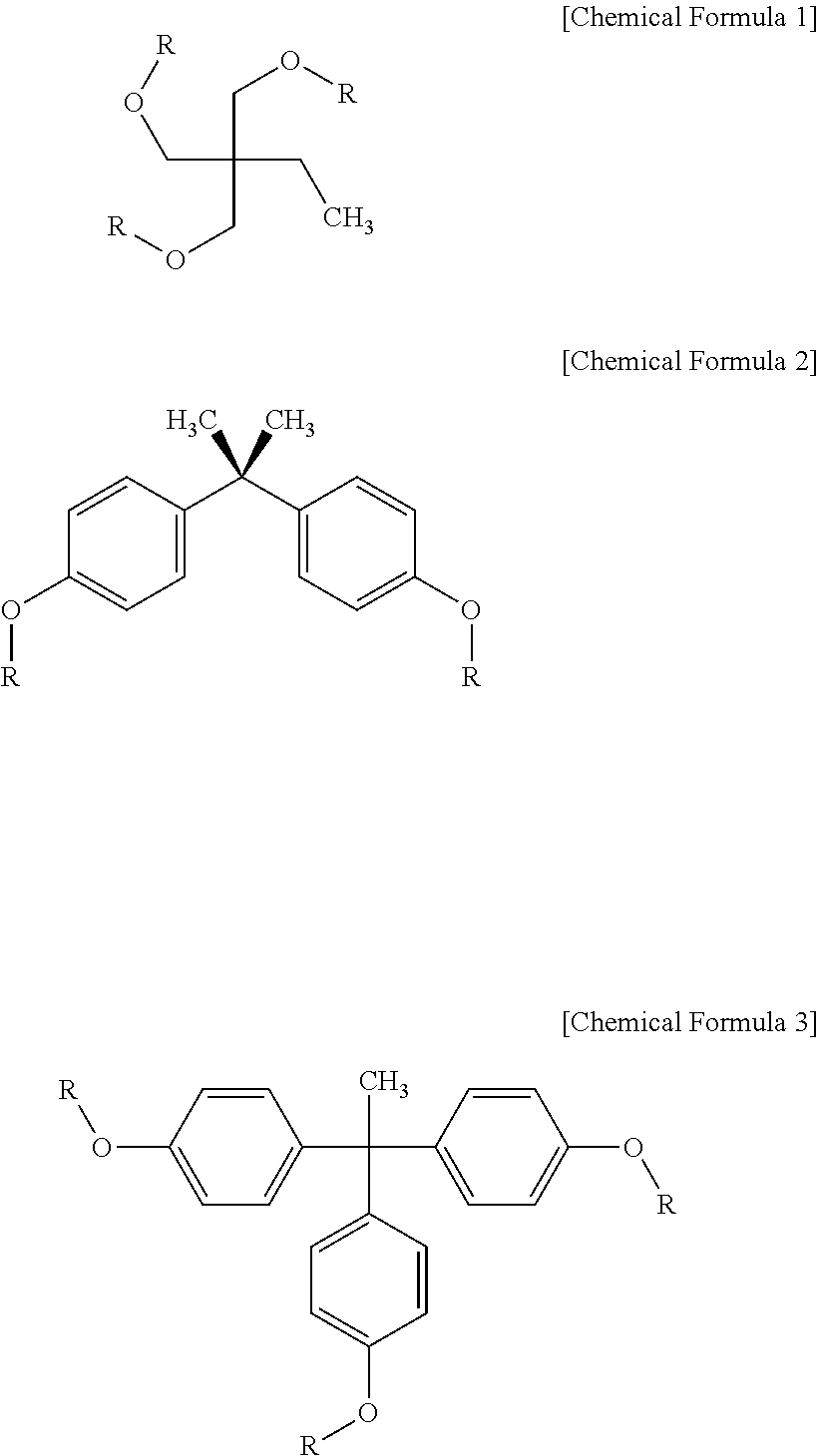
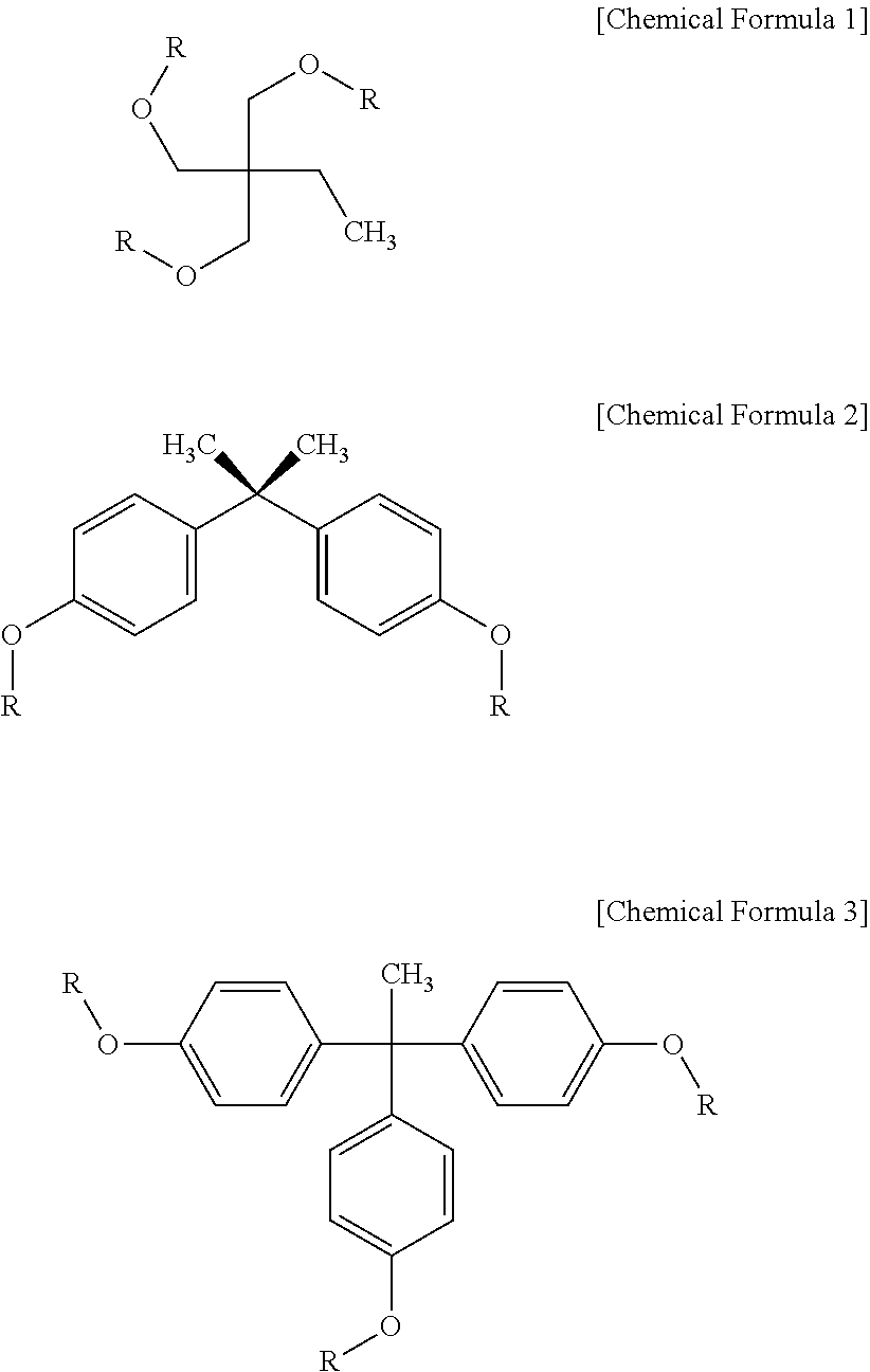
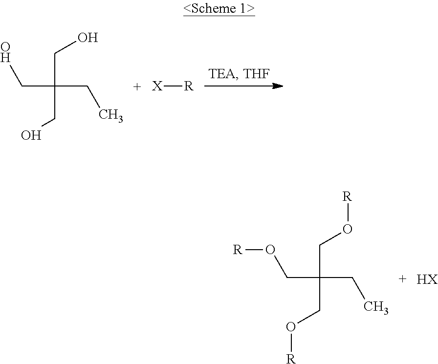
[0056]In a three-neck 500 ml round-bottom flask equipped with an argon reflux device, 13.4 g of 2-ethyl-2-hydroxymethyl-1,3-propanediol, 52.2 g of triethylamine and 200 ml of anhydrous tetrahydrofuran were placed and stirred using a magnetic bar. Stirring was performed for 10 min in an argon atmosphere, after which 31.6 g of acryloyl chloride was slowly added over 10 min using a dropping funnel and then stirred at room temperature for 2 hr, and the resulting reaction product was filtered and then washed with water two times. The filtered product was completely dissolved in 150 ml of chloroform and then purified five times using a 500 ml separatory funnel. Thereafter, the product, dissolved in chloroform, was further purified through column chromatography using a solvent comprising methylene chloride and hexane at a content ratio of 1:1 to remove unreacted materials, ultimately yielding a white solid product having a weight average molecule weight of 204, as represented by Chemical F...

substitution example 2

[0057]In a three-neck 500 ml round-bottom flask equipped with an argon reflux device, 22.8 g of bisphenol A, 37.2 g of triethylamine and 200 ml of anhydrous tetrahydrofuran were placed and stirred using a magnetic bar. Stirring was performed for 10 min in an argon atmosphere, after which 22.6 g of acryloyl chloride was slowly added over 10 min using a dropping funnel and then stirred at room temperature for 2 hr, and the resulting reaction product was filtered and then washed with water two times. The filtered product was completely dissolved in 150 ml of chloroform and then purified five times using a 500 ml separatory funnel. Thereafter, the product, dissolved in chloroform, was further purified through column chromatography using a solvent comprising methylene chloride and hexane at a content ratio of 1:1 to remove unreacted materials, ultimately yielding a white solid product having a weight average molecule weight of 298, as represented by Chemical Formula 2 (R: acryloyl). Base...

substitution example 3

[0058]In a three-neck 500 ml round-bottom flask equipped with an argon reflux device, 30.6 g of 1,1,1-tri(4-hydroxyphenyl)ethane, 52.2 g of triethylamine and 200 ml of anhydrous tetrahydrofuran were placed and stirred using a magnetic bar. Stirring was performed for 10 min in an argon atmosphere, after which 31.6 g of acryloyl chloride was slowly added over 10 min using a dropping funnel and then stirred at room temperature for 2 hr, and the resulting reaction product was filtered and then washed with water two times. The filtered product was completely dissolved in 150 ml of chloroform and then purified five times using a 500 ml separatory funnel. Thereafter, the product, dissolved in chloroform, was further purified through column chromatography using a solvent comprising methylene chloride and hexane at a content ratio of 1:1 to remove unreacted materials, ultimately yielding a white solid product having a weight average molecule weight of 376, as represented by Chemical Formula ...


PUM

PropertyMeasurementUnit
wavelength rangeaaaaaaaaaa
wavelengthaaaaaaaaaa
sizeaaaaaaaaaa

Abstract

Provided is a negative photoresist composition for a KrF laser for semiconductor pattern formation, which includes a predetermined compound in order to improve the properties of a conventional negative photoresist, thereby realizing high transparency, high resolution and an excellent profile, even in the presence of an exposure source having a short wavelength compared to the conventional negative photoresist, and is thus suitable for use in semiconductor processing.

Description

TECHNICAL FIELD[0001]The present invention relates to a negative photoresist composition for a KrF laser for semiconductor pattern formation.BACKGROUND ART[0002]With the recent demand to reduce the size and increase the degree of integration of semiconductor devices through the development of semiconductor manufacturing technology, techniques for forming ultrafine patterns having line widths corresponding to tens of nm or less are required. Advances in techniques for forming ultrafine patterns have been made by the use of light sources having smaller wavelengths and through the development of processing technology and photoresists suitable for such light sources.[0003]A photoresist is used for photolithography for forming a variety of patterns. The term “photoresist” refers to a photosensitive resin, the solubility of which varies in a developing solution due to the action of light, to thus obtain an image corresponding to the exposure pattern.[0004]The formation of a photoresist pa...

Claims


Application Information

Patent Timeline
Patent Type & Authority Patents(United States)
IPC IPC(8): G03F7/004G03F7/038G03F7/033
CPCG03F7/0382G03F7/004G03F7/0384G03F7/033G03F7/038G03F7/0045
Inventor LEE, SEUNG HUNLEE, SEUNG HYUNYOON, SANG WOONGLEE, SU JINCHOI, YOUNG CHEOL
Owner YCCHEM CO LTD
Why Eureka
Try Eureka