Non-contact surgical adapter electrical interface

a non-contact, electrical interface technology, applied in the direction of surgical staples, surgical forceps, transportation and packaging, etc., can solve the problem of easy damage to galvanic electrical connections

Active Publication Date: 2018-12-25
TYCO HEALTHCARE GRP LP
View PDF477 Cites 517 Cited by
  • Summary
  • Abstract
  • Description
  • Claims
  • Application Information

AI Technical Summary

Problems solved by technology

However, galvanic electrical connections are susceptible to damage from the steam and the high-pressure used in the autoclave process.

Method used


Image

  • Non-contact surgical adapter electrical interface
  • Non-contact surgical adapter electrical interface
  • Non-contact surgical adapter electrical interface

Examples


Embodiment Construction

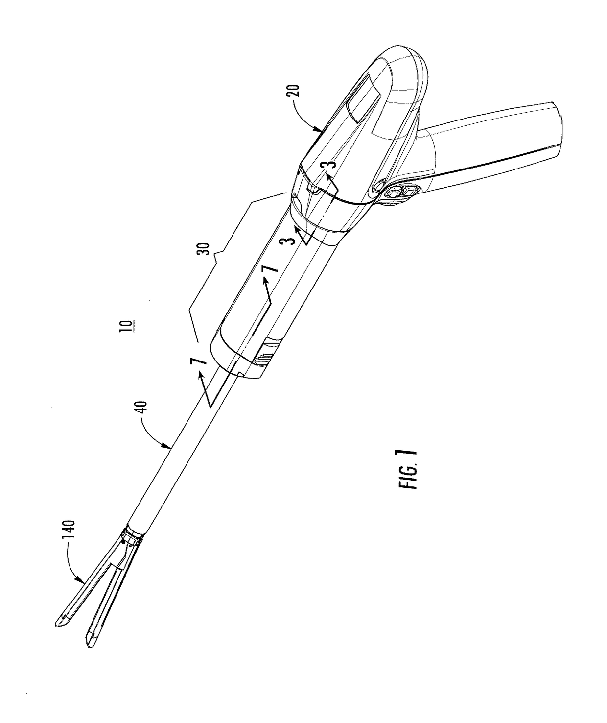
[0025]Embodiments of the present disclosure are now described in detail with reference to the drawings in which like reference numerals designate identical or corresponding elements in each of the several views. As used herein, the term “clinician” refers to a doctor, a nurse, or any other care provider and may include support personnel. Throughout this description, the term “proximal” refers to the portion of the device or component thereof that is closest to the clinician and the term “distal” refers to the portion of the device or component thereof that is farthest from the clinician.

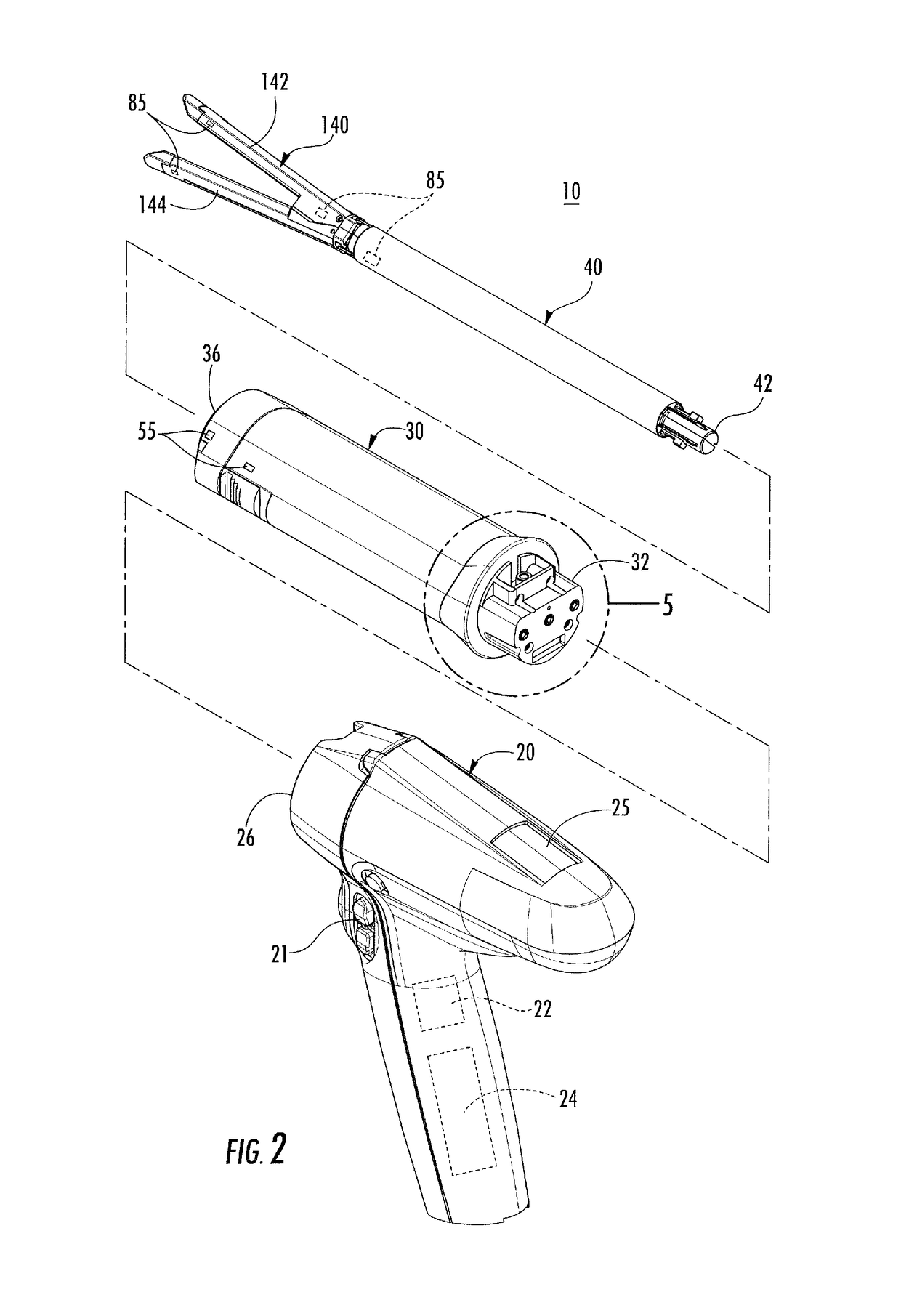
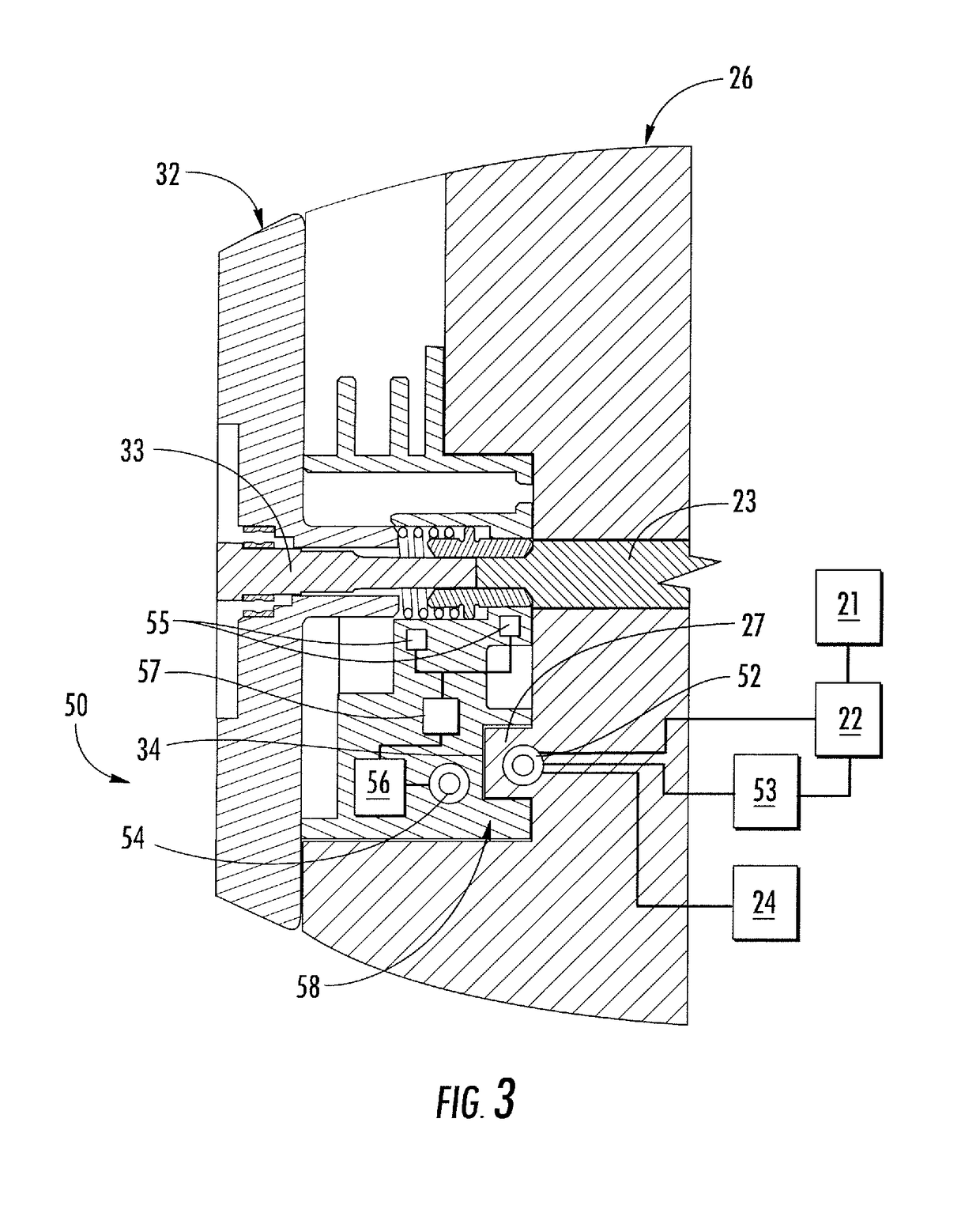
[0026]Referring now to FIGS. 1-3, a surgical instrument 10 is provided in accordance with the present disclosure including a handle 20, an adaptor 30, and a disposable loading unit 40. The adaptor 30 includes a handle connector 32 at a proximal end thereof and the handle 20 defines an adaptor receiver 26 for receiving the handle connector 32 to releasably couple the adaptor 30 to the handle 20. The d...


PUM


Abstract

A surgical instrument includes a handle, an adaptor, and a non-contact electrical interface. A proximal end of the adaptor is releasably coupled to a distal end of the handle. The non-contact electrical interface is configured to wirelessly transmit energy from the handle to the adaptor and is configured to wirelessly transmit data from the adaptor to the handle. The electrical interface may include a proximal coil disposed within the handle and a distal coil disposed within the adaptor. When the adaptor is coupled to the handle, the proximal coil may be disposed adjacent the distal coil to form a transformer to inductively transfer energy from the handle to the adaptor and inductively transmit data from the adaptor to the handle.

Description

CROSS-REFERENCE TO RELATED APPLICATIONS[0001]This application claims the benefit of and priority to U.S. Provisional Patent Application No. 61 / 980,724, filed Apr. 17, 2014, the entire disclosure of which is incorporated by reference herein.BACKGROUND[0002]1. Technical Field[0003]The present disclosure relates to surgical instruments and, more specifically, to non-contact electrical interfaces for surgical instruments.[0004]2. Discussion of Related Art[0005]Powered surgical instruments generally have a handle portion and a working portion extending from the handle portion that contacts a patient. The working portion may require energy to power elements thereof and may gather data from a plurality of sensors thereof. Power may be transferred from the handle portion to the working portion and data may be transferred from the working portion to the handle portion through an electrical interface. Traditionally the electrical interface includes galvanic electrical connections allowing the...

Claims


Application Information

Patent Timeline
Patent Type & Authority Patents(United States)
IPC IPC(8): A61B17/00H02J50/10H02J7/02A61B90/98A61B17/072H02J5/00H04B5/00A61B90/00
CPCH02J50/10A61B17/07207A61B90/98H02J5/005H02J7/025H04B5/0037H04B5/0081A61B17/00A61B2090/0811A61B2017/00022A61B2017/0046A61B2017/00075A61B2017/00084A61B2017/00199A61B2017/00221A61B2017/00398A61B2017/00411A61B2017/00473A61B2017/00477A61B2017/00734H02J2310/23A61B17/295
Inventor CALDERONI, ANTHONY
Owner TYCO HEALTHCARE GRP LP
Why Eureka
Try Eureka