Method and device for processing stereoscopic data

a stereoscopic and data technology, applied in the field of stereoscopic data processing, can solve problems such as incorrect detection or non-detection of objects

Active Publication Date: 2018-12-25
ROBERT BOSCH GMBH
View PDF35 Cites 3 Cited by
  • Summary
  • Abstract
  • Description
  • Claims
  • Application Information

AI Technical Summary

Benefits of technology

[0005]An object on which the invention is based can be seen as that of furnishing a method that enables simple classification of objects of a surroundings of a stereo sensor system.

Problems solved by technology

If errors occur in the estimation of the plane, however, the direct result is generally that objects are incorrectly detected or not detected.

Method used


Image

  • Method and device for processing stereoscopic data
  • Method and device for processing stereoscopic data
  • Method and device for processing stereoscopic data

Examples


Embodiment Construction

[0049]Identical reference characters can be used below for identical features.

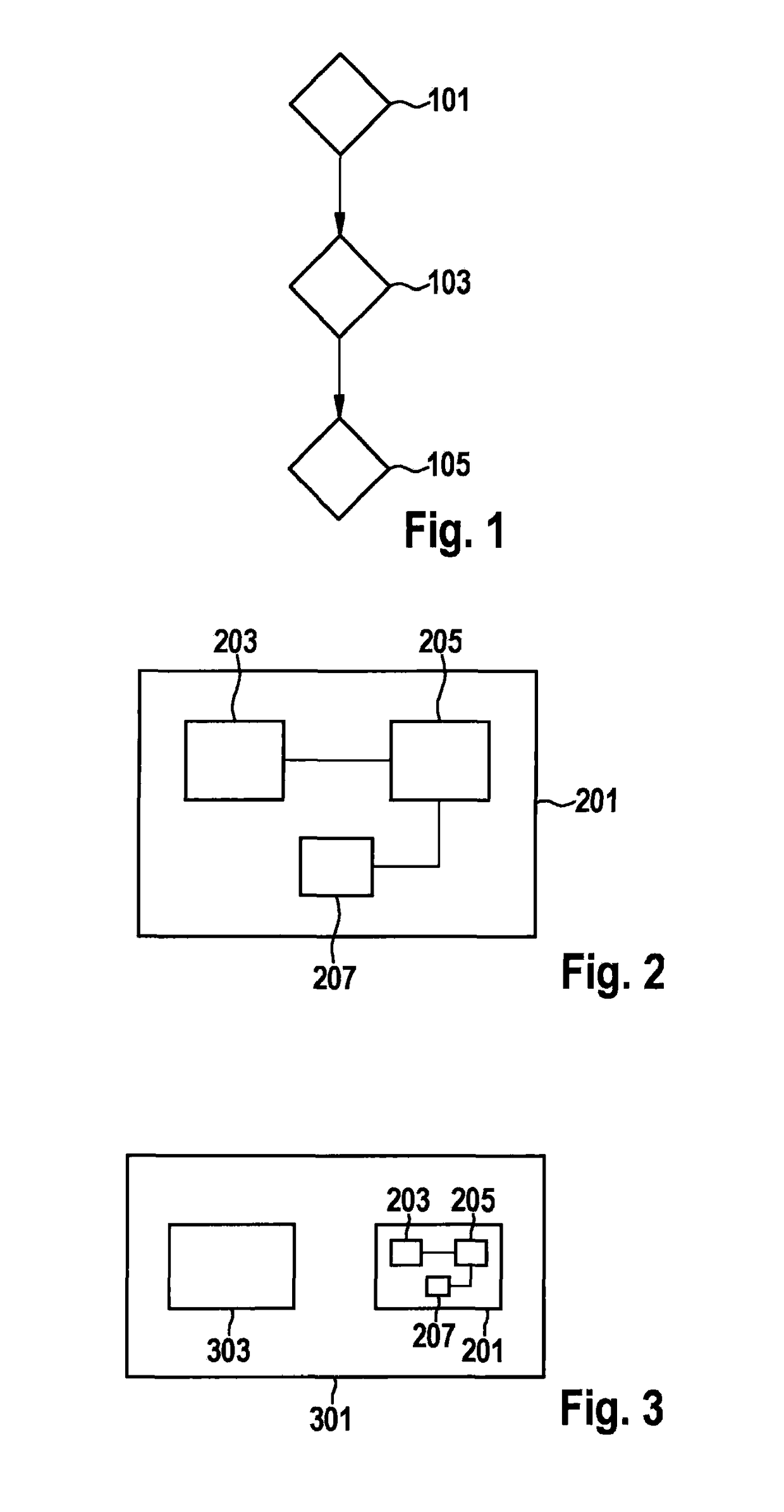
[0050]FIG. 1 is a flow chart of a method for processing or manipulating sensor data of a stereo sensor system for stereoscopic sensing of an environment of the stereo sensor system.

[0051]In a step 101 a disparity map is constituted based on the sensor data of the stereo sensor system. In a step 103 a change in disparity between two disparity points of the disparity map which are constituted at a spacing from one another is identified. As a function of the change in disparity, at least one of the two disparity points is classified to correspond to an object according to a step 105. This therefore means in particular that an object allocated to the disparity point is classified. This therefore means, for example, that the object is classified as an obstacle or as an open area or a travelable area or as an object that can be traveled under, for example a bridge.

[0052]FIG. 2 shows an apparatus 201 for processi...


PUM


Abstract

A method is described for processing sensor data of a stereo sensor system for stereoscopic sensing of an environment of the stereo sensor system. A disparity map is constituted based on the sensor data, wherein a change in disparity between two disparity points of the disparity map that are constituted with a spacing from one another is identified, at least one of the two disparity points being classified to correspond to an object as a function of the change in disparity. Also described is a corresponding apparatus, to a corresponding object recognition system, and to a corresponding computer program.

Description

FIELD OF THE INVENTION[0001]The present invention relates to a method and an apparatus for processing or manipulating sensor data of a stereo sensor system for stereoscopic sensing of an environment of the stereo sensor system. The invention further relates to an object recognition system and to a computer program.BACKGROUND INFORMATION[0002]Driver assistance systems as a rule require sensors in order to sense obstacles and identify an open area in the vehicle's surroundings. Stereo cameras that encompass two horizontally offset cameras are used, inter alia, for this. The result of this disposition is that objects are observed in horizontally offset fashion in the camera images as well; the offset, or so-called “disparity,” becomes smaller for remote objects and larger for objects in the close-in region, with reference to the cameras. For each object, its distance from the observer (i.e. in this case the stereo camera) can consequently be identified from the disparity.[0003]German P...

Claims


Application Information

Patent Timeline
Patent Type & Authority Patents(United States)
IPC IPC(8): H04N13/128G06K9/00B60R1/00H04N13/239H04N13/00
CPCH04N13/128B60R1/002G06K9/00805H04N13/239H04N2013/0081B60R2300/107B60R2300/303B60R2300/8093B60R2300/105G06V20/58
Inventor BUERKLE, LUTZPINK, OLIVER
Owner ROBERT BOSCH GMBH
Why Eureka
Try Eureka