Force-measuring device with sliding weight

A force measuring device and weight measurement technology, which is applied in the direction of measuring devices, counterweight scales, detailed information of weighing equipment, etc., can solve problems such as shifting of measurement windows, and achieve the effect of simplifying classification

Active Publication Date: 2014-02-12
METTLER TOLEDO INC
View PDF11 Cites 9 Cited by
  • Summary
  • Abstract
  • Description
  • Claims
  • Application Information

AI Technical Summary

Problems solved by technology

This will cause the measurement window to be shifted only in large jumps

Method used


Image

  • Force-measuring device with sliding weight
  • Force-measuring device with sliding weight
  • Force-measuring device with sliding weight

Examples


Embodiment Construction

[0055] Features with the same function and similar arrangement are denoted by the same reference numerals below. The following description covers the measuring principle, the principle of the push system and the principle of the push-pull system.

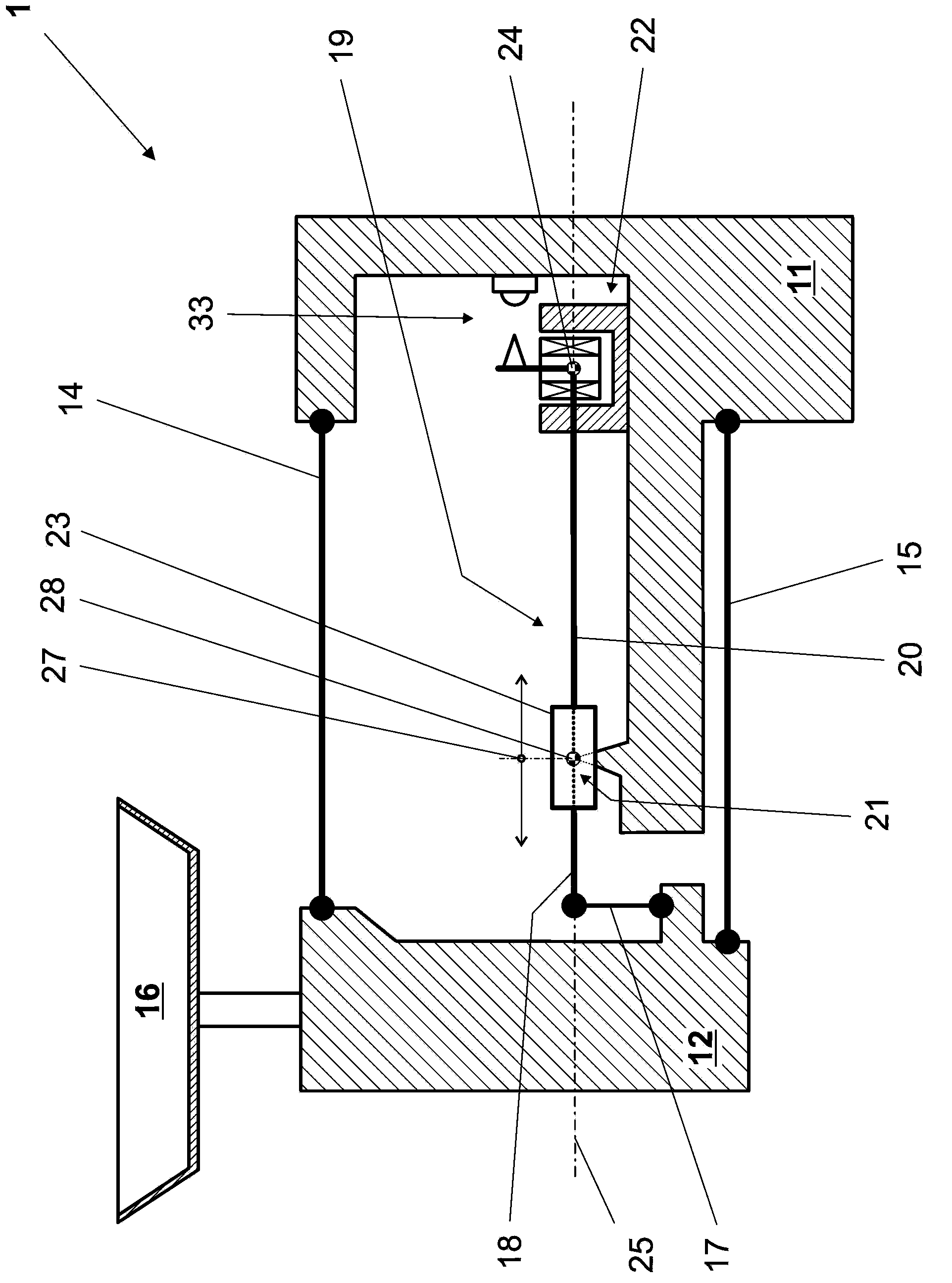
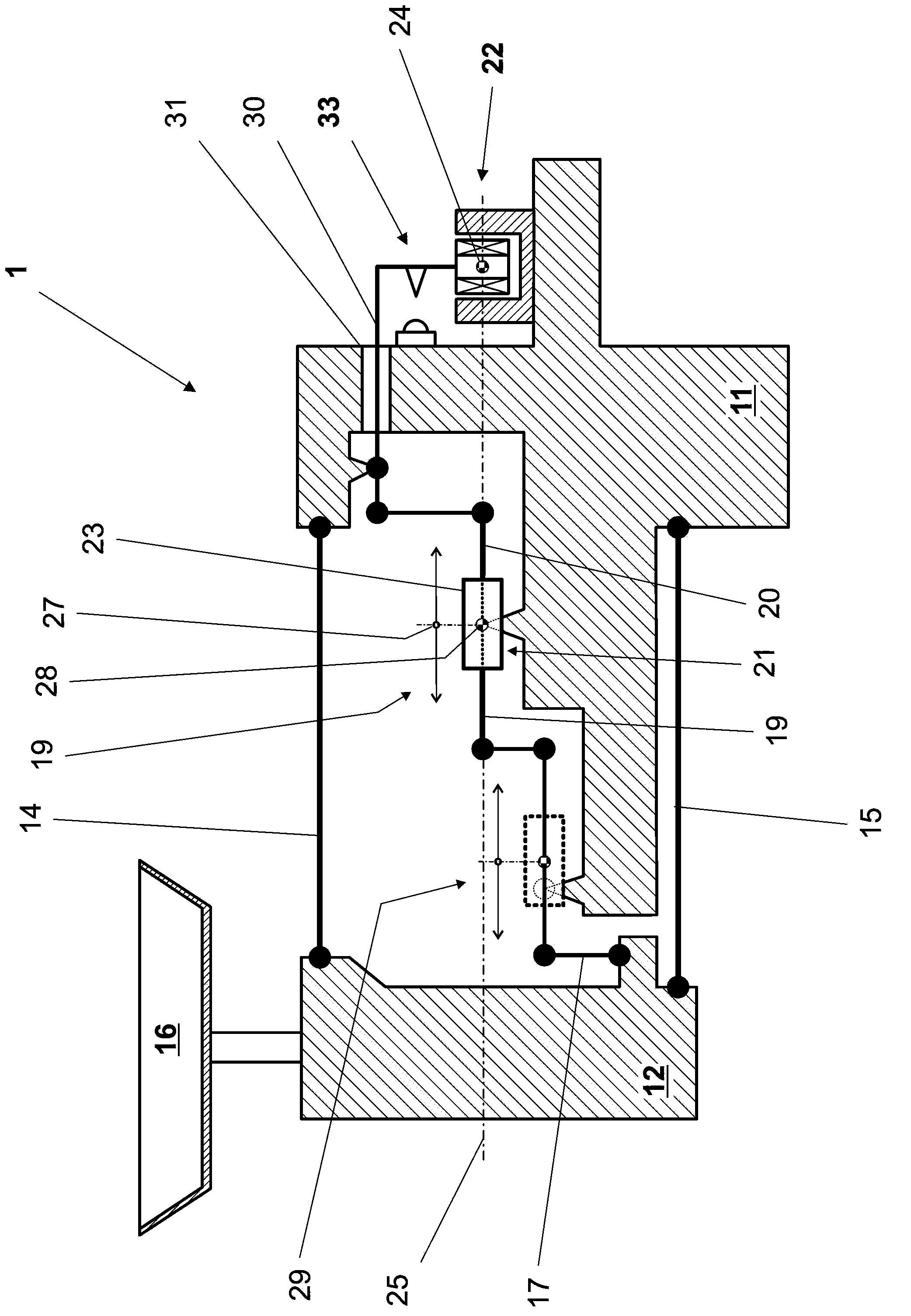
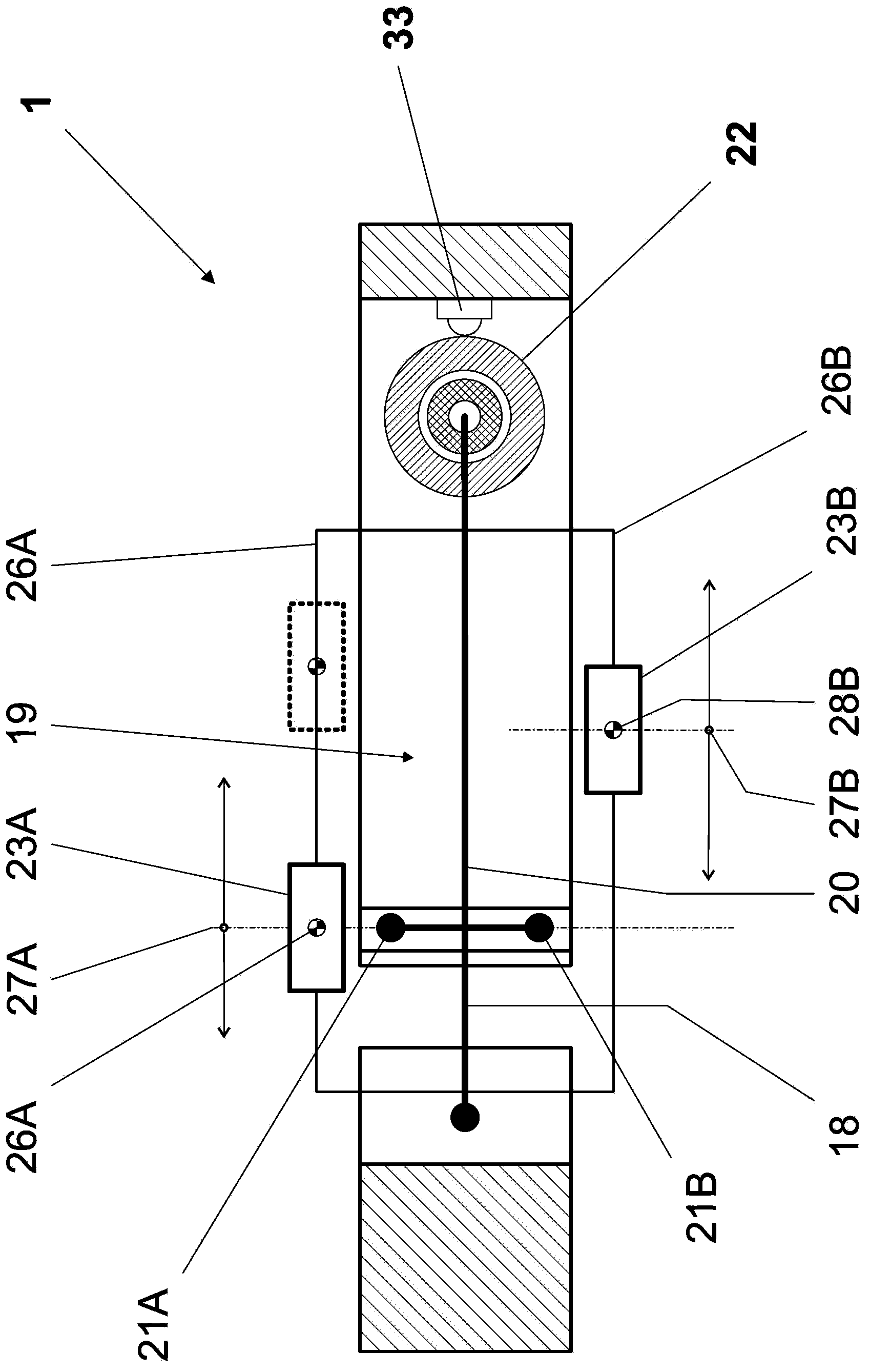
[0056] figure 1 The force-measuring device 1 according to the invention is schematically shown in a side sectional view. The force-measuring device 1 stands by its fixing part 11 on a support structure. The load receiving part 12 connected to the fixed part 11 by means of two parallel guides 14 and 15 carries a weighing pan 16 on which a weighing load is placed. The invention is not limited to the shown configuration with the weighing pan on top. The force measuring device can also be equipped with a suspended weighing pan. The link 17 transmits the force of gravity to the first lever arm 18 of the balance beam 19 which is pivotally supported at the pivot 21 (at figure 1 concealed behind the sliding counterweight 23), wherein t...


PUM


Abstract

A force-measuring device (1) for a gravimetric measuring instrument has a stationary part (11) and a load-receiving part (12). Parallel guide members (14, 15) connect the receiving parts. The device also has at least one balance beam (19) connected to the load-receiving part through a coupling member (17) acting on a first lever arm (18) thereof, and which, at a second lever arm (20) thereof, is connected to a measurement transducer (22) which is arranged on the stationary part. Further levers (29, 30) can be arranged, respectively, between the first lever arm and the load-receiving part, and between the second lever arm and the measurement transducer. At least one sliding weight (23, 23A, 23B) is arranged on the at least one balance beam, wherein the position of each of the sliding weights present can be varied in a controlled way by means of at least one drive mechanism.

Description

technical field [0001] The invention relates to a force measuring device for a gravimetric measuring instrument having a sliding weight arranged on a balance beam and slidable along said balance beam. Background technique [0002] In weighing cells that function according to the principle of electromagnetic force compensation and are also called magnetic return weighing cells or MFR weighing cells, the weight of the object being weighed is transmitted directly or via one or more force transfer levers to the electromechanical measurement transducer, said electromechanical measuring transducer generates a compensating force corresponding to the weight of the weighing object and at the same time transmits an electrical signal which is further processed by the electronic weighing module in the processor unit and indicated at on the display panel. [0003] In MFR weighing cells, the weight of the object to be weighed is measured via an electrical substitute. For various technic...

Claims


Application Information

Patent Timeline
Patent Type & Authority Applications(China)
IPC IPC(8): G01G1/38
CPCG01G21/26G01G23/16G01G7/02G01G21/24G01G1/18
Inventor A·梅茨格S·巴尔蒂斯伯格H-R·布克哈德
Owner METTLER TOLEDO INC
Why Eureka
Try Eureka