Surface cleaning apparatus

a cleaning apparatus and surface technology, applied in the direction of suction handles, vacuum cleaners, domestic applications, etc., can solve the problems of inability to provide the suction motor of the portable cleaning unit, the inability to maneuver the upright vacuum cleaner in smaller or crowded areas, and the inability to provide the suction motor. , to achieve the effect of increasing stability, increasing maneuverability, and increasing stability

Active Publication Date: 2019-01-01
OMACHRON INTPROP
View PDF400 Cites 9 Cited by
  • Summary
  • Abstract
  • Description
  • Claims
  • Application Information

AI Technical Summary

Benefits of technology

[0007]According to one broad aspect of this invention, a surface cleaning apparatus comprises a portable cleaning unit, which may be carried by hand or a shoulder strap such as a pod or handvac (hand vacuum cleaner), which is removably mounted on an upright section that is moveably mounted to a surface cleaning head between a storage position and a reclined in use position. The upright section may be an up flow duct or conduit which is rigid and suitable to support the pod or handvac. The portable cleaning unit may be provided with a suction motor (a portable cleaning unit suction motor) and an energy storage member (such as one or more battery). Accordingly, the suction motor of the portable cleaning unit may be operable on DC current. However, in accordance with this embodiment, the surface cleaning head or the upright section, and preferably the surface cleaning head, may include a second or upstream suction motor (e.g. an AC powered suction motor). Accordingly, when the portable cleaning unit is provided on the upright section and the surface cleaning head and / or the upright section is connected to a source of current, the upstream suction motor may be operated, e.g. on AC current, and used to cause air to travel through an airflow path (e.g., push the air in the case of a dirty air motor) to the air treatment member in the portable cleaning unit. An advantage of this design is that the upstream suction motor may provide more air watts than a smaller motor provided in the portable cleaning unit so as to produce a higher airflow and therefore increase cleanability when the portable cleaning unit is provided on the upright section. Alternately, or in addition, the upstream suction motor, when combined with the portable cleaning unit suction motor, may provide more air flow and air watts than the portable cleaning unit suction motor alone and therefore provide increased cleanability. However, when the portable cleaning unit is removed from the upright section, a smaller and lighter suction motor is utilized. While the velocity of the airflow through the portable cleaning unit when removed from the upright section may be decreased, the reduced weight of the suction motor may be beneficial. In addition, a smaller airflow path may be provided when the portable cleaning unit is removed from the upright section, and, accordingly, a smaller AC or DC power suction motor may provide substantially similar airflow in the hand carriable mode.
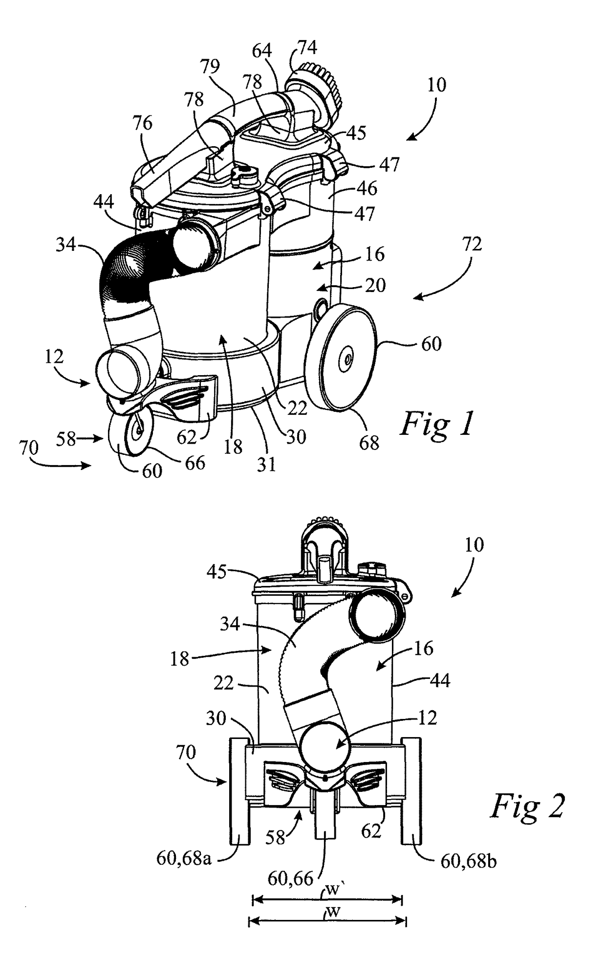
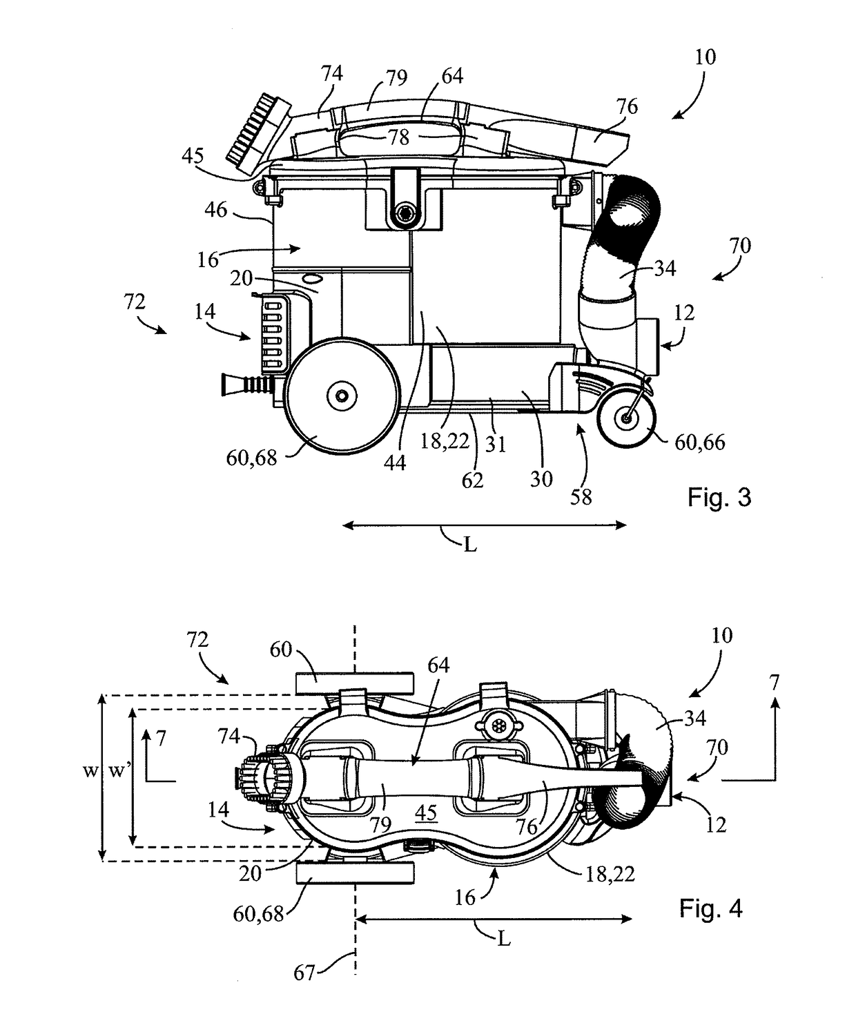
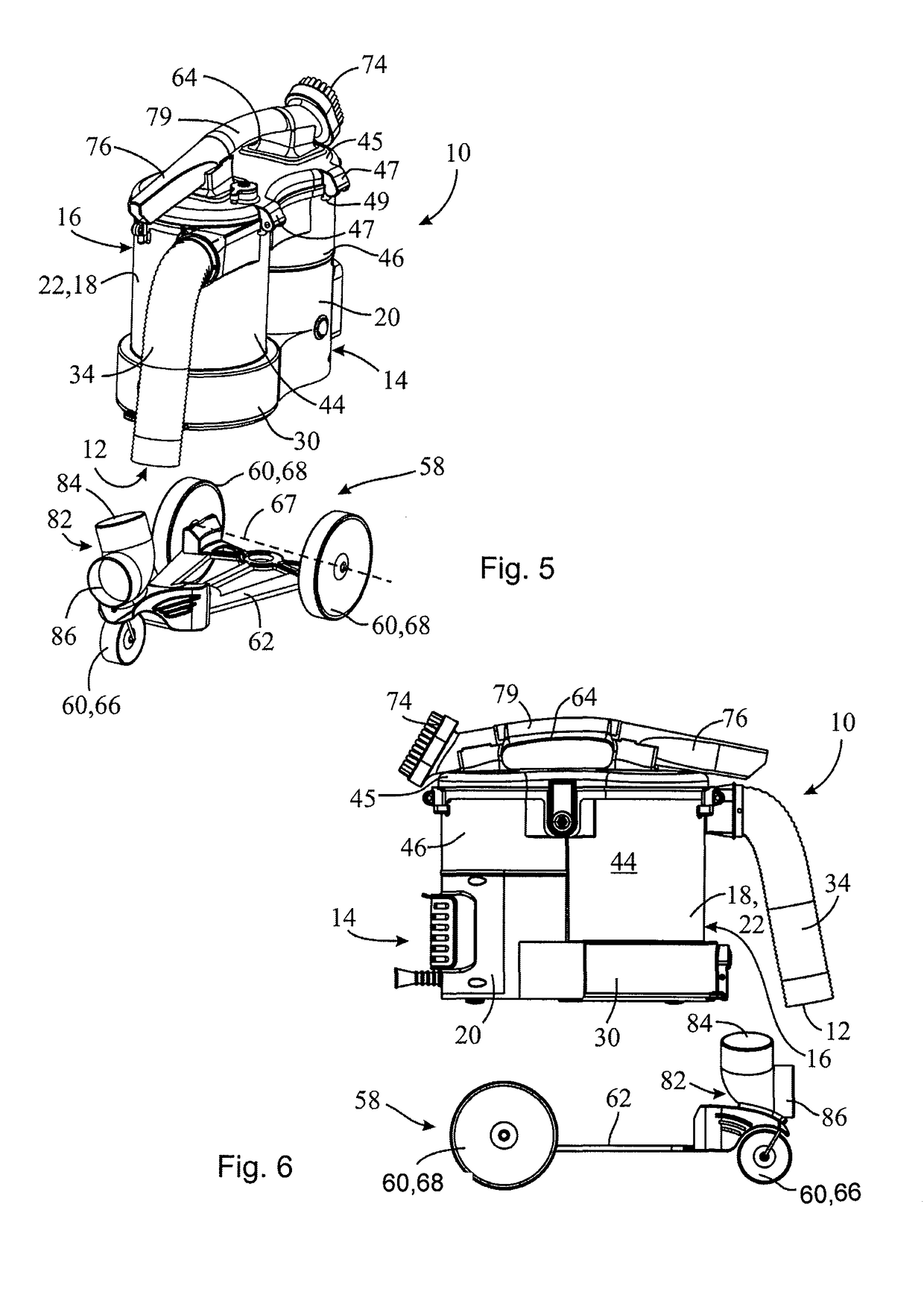
[0093]In some embodiments, the wheeled base may have rear wheels that are positioned outwardly of an area occupied by the cleaning unit when the cleaning unit is mounted on the wheeled base. Alternately, or in addition, the wheeled base may have front wheels that are positioned outwardly of an area occupied by the cleaning unit when the cleaning unit is mounted on the wheeled base. Such embodiments may be advantageous because the wheeled base may have a relatively wide stance, thereby providing greater stability to the surface cleaning apparatus. Additionally, the surface cleaning apparatus may be relatively close to the ground, and may therefore have a lower center of mass and increased stability.

Problems solved by technology

However, depending on the size of the surface cleaning head, an upright vacuum cleaner may not be useable in smaller or crowded areas.
However, consumers must separately move a canister body, which can add an extra step during the cleaning process.
In some embodiments, the suction motor in the portable cleaning unit may not be used to provide motive power to move fluid through the fluid flow path when the surface cleaning unit is switched on and when the portable cleaning unit is mounted on the wheeled base.

Method used


Image

  • Surface cleaning apparatus
  • Surface cleaning apparatus
  • Surface cleaning apparatus

Examples


Embodiment Construction

[0162]Various apparatuses or processes will be described below to provide an example of an embodiment of each claimed invention. No embodiment described below limits any claimed invention and any claimed invention may cover processes or apparatuses that differ from those described below. The claimed inventions are not limited to apparatuses or processes having all of the features of any one apparatus or process described below or to features common to multiple or all of the apparatuses described below. It is possible that an apparatus or process described below is not an embodiment of any claimed invention. Any invention disclosed in an apparatus or process described below that is not claimed in this document may be the subject matter of another protective instrument, for example, a continuing patent application, and the applicants, inventors or owners do not intend to abandon, disclaim or dedicate to the public any such invention by its disclosure in this document.

[0163]It will be ...


PUM


Abstract

A surface cleaning apparatus comprises a surface cleaning head, an upright section moveably mounted to the surface cleaning head, and a portable cleaning unit removably mounted to the upright section and comprising an energy storage member and a portable cleaning unit suction motor. The energy storage member provides the portable cleaning unit suction motor with power at least when the portable cleaning unit is switched on and when the portable cleaning unit is removed from the upright section.

Description

CROSS-REFERENCES TO RELATED APPLICATIONS[0001]This application claims the benefit under 35 USC 120 as:(a) a continuation-in-part of U.S. patent application Ser. No. 14 / 822,211, which was filed on Aug. 10, 2015 and which itself claims priority from U.S. Provisional Patent Application 62 / 093,189 which was filed on Dec. 17, 2014;[0002](b) as continuation-in-part of U.S. patent application Ser. No. 14 / 875,381, which was filed on Oct. 5, 2015 and which itself is continuation of U.S. patent application Ser. No. 13 / 782,217 which was filed on Mar. 1, 2013 and which issued as U.S. Pat. No. 9,192,269 on Nov. 24, 2015, which itself is a continuation-in-part of U.S. patent application Ser. No. 13 / 720,754 which was filed on Dec. 19, 2012 and which issued as U.S. Pat. No. 8,752,239 on May 2, 2013, which itself is a divisional application of U.S. patent application Ser. No. 11 / 954,331 which was filed on Dec. 12, 2007 which issued as U.S. Pat. No. 8,359,705 on Jan. 29, 2013, which itself claims pri...

Claims


Application Information

Patent Timeline
Patent Type & Authority Patents(United States)
IPC IPC(8): A47L5/24A47L9/28A47L5/22A47L5/28A47L9/32A47L9/16
CPCA47L5/225A47L5/24A47L5/28A47L9/1625A47L9/325A47L9/1691A47L9/2868A47L9/2878A47L9/2884A47L9/1683
Inventor CONRAD, WAYNE ERNEST
Owner OMACHRON INTPROP
Why Eureka
Try Eureka