Pneumatic tire

a technology of pneumatic tires and tyres, applied in the direction of tyre tread bands/patterns, vehicle components, transportation and packaging, etc., can solve the problems of affecting the effect of reducing the number of pneumatic tires, affecting the performance of ground contact, and affecting the quality of pneumatic tires, etc., to achieve the effect of suppressing the toppling of the surface portion

Inactive Publication Date: 2019-01-01
TOYO TIRE & RUBBER CO LTD
View PDF17 Cites 1 Cited by
  • Summary
  • Abstract
  • Description
  • Claims
  • Application Information

AI Technical Summary

Benefits of technology

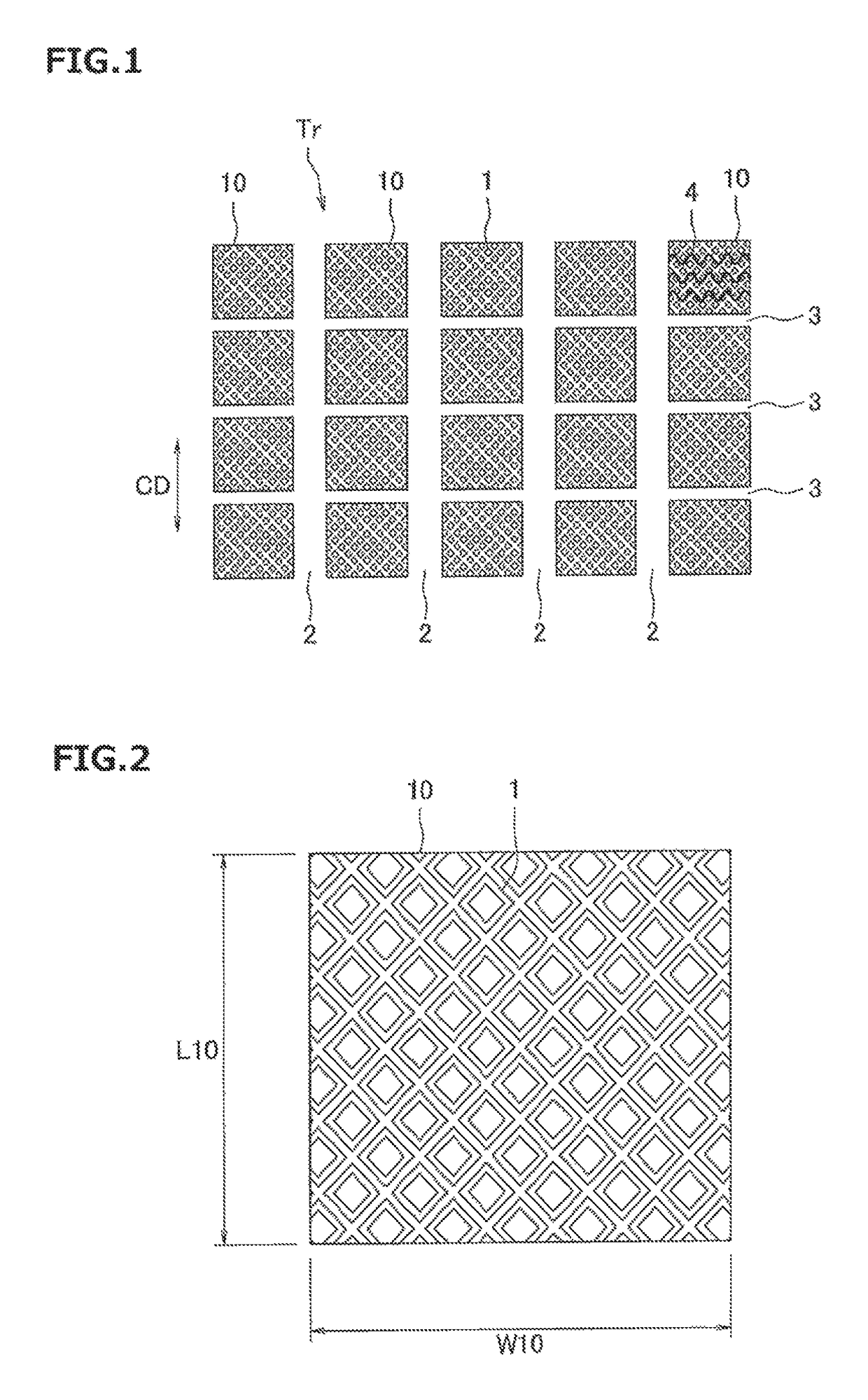
[0011]The present invention is made by taking the above actual condition into consideration, and an object of the present invention is to provide a pneumatic tire which can suppress toppling of a surface portion of a land portion on which shallow grooves are formed.
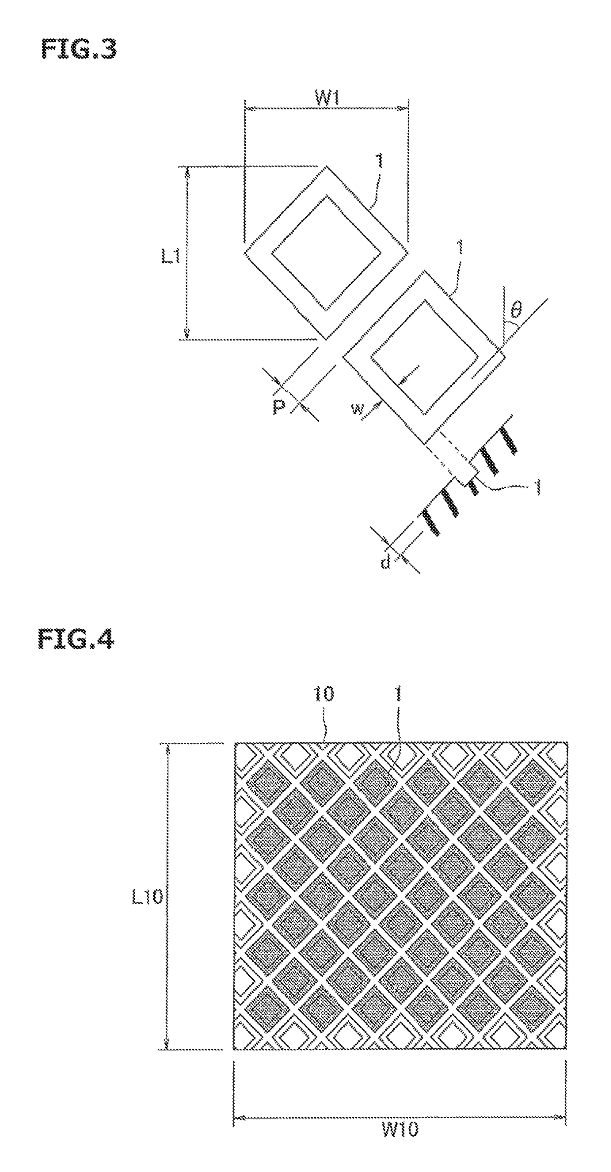
[0012]The object can be achieved by the following present invention. The present invention provides a pneumatic tire comprising a plurality of polygonal shallow grooves, formed on a surface of a land portion of a tread surface, for constructing closed loops, wherein the plurality of polygonal shallow grooves formed on one of the land portions have internal regions which are independent of each other. According to the structure, it is possible to suppress reduction of a rigidity in the surface portion of the land portion, and thus to suppress the toppling of the surface portion of the land portion at the braking time or the turning time. As a result, it is possible to lighten deterioration of the ground contact performance, and the edge effect caused by the shallow grooves can be appropriately achieved, thereby improving the traveling performance on the ice road surface or the wet road surface.
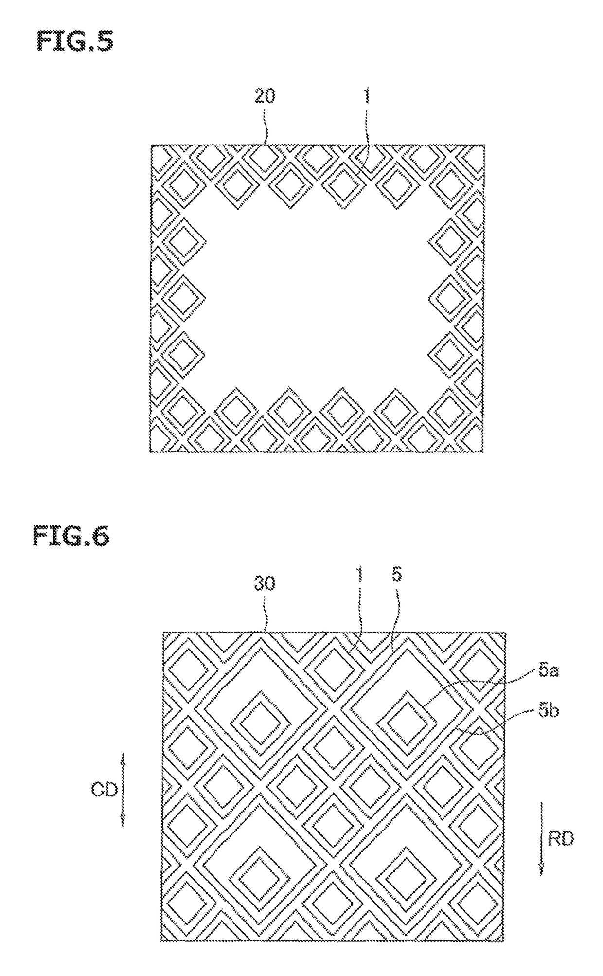
[0014]The polygonal shallow grooves may have a structure in which a plurality of closed loops are arranged in a nested shape. In this case, if the inside closed loop is adapted to be eccentric in a leading side in relation to the outside closed loop in the polygonal shallow groove having the structure in which the rotating direction is designated and a plurality of closed loops are arranged in a nested shape, it is possible to enhance the effect of suppressing the toppling of the surface portion of the land portion at the braking time.

Problems solved by technology

However, since the formation of the shallow grooves lowers a rigidity of the surface portion of the land portion, the surface portion of the land portion tends to locally topple at the braking time or the turning time.
As a result, a ground contact performance is deteriorated, and there is a case that an edge effect caused by the shallow grooves can not be sufficiently achieved.
However, it is difficult to densely arrange a plurality of cuts each having the oval shape.

Method used


Image

  • Pneumatic tire
  • Pneumatic tire
  • Pneumatic tire

Examples


examples

[0053]An example which concretely shows the structure and effect of the present invention will be explained. An evaluation of each of performances is executed as follows.

(1) Ice Braking Performance

[0054]A test tire was attached to a vehicle (4WD middle sedan car of 1500 cc class) and was charged with a pneumatic pressure 220 kPa, a braking distance when an ABS was actuated by applying a braking force at a speed 40 km / h while the vehicle travels on an ice road surface was measured, and an inverse number thereof was calculated. Results are indicated by an index number on the assumption that a result of a comparative example 1 is set to 100, and as the numerical value is larger, the ice braking performance is more excellent.

(2) Ice Turning Performance

[0055]A test tire was attached to a vehicle (4WD turning measurement vehicle of 2491 cc class) and was charged with the pneumatic pressure 220 kPa, a linear travel was performed at a speed 20 km / h by traveling on the ice road surface, and ...


PUM


Abstract

A pneumatic tire has a plurality of polygonal shallow grooves. The polygonal shallow grooves are formed on a surface of a land portion of a tread surface, for constructing closed loops. The plurality of polygonal shallow grooves formed on one of the land portions have internal regions which are independent of each other.

Description

BACKGROUND OF THE INVENTION[0001]Field of the Invention[0002]The present invention relates to a pneumatic tire in which shallow grooves are formed on a surface of a land portion of a tread surface.[0003]Description of the Related Art[0004]In a winter tire or an all-season tire, a rubber having a high friction coefficient is employed in a tread surface for the purpose of enhancing a traveling performance on an ice road surface. However, in order to sufficiently achieve an effect thereof, a running-in travel for about several hundreds of km is required. Accordingly, in order to achieve the performance from an initial state in which the running-in travel is not performed, there has been known an application of a so-called first edge process which forms shallow grooves on a surface of a land portion of the tread surface. Even in a summer tire, there is a case that the first edge process is applied for the purpose of improving the traveling performance on a wet road surface.[0005]As the ...

Claims


Application Information

Patent Timeline
Patent Type & Authority Patents(United States)
IPC IPC(8): B60C11/12B60C11/03B60C11/11
CPCB60C11/1204B60C11/032B60C11/1259B60C11/11B60C2011/1254
Inventor ASAYAMA, YOSHINORI
Owner TOYO TIRE & RUBBER CO LTD
Why Eureka
Try Eureka