Headrest support structure
A headrest and structure technology, applied in the field of headrest support structure, can solve problems such as support deformation, achieve the effect of suppressing deformation and improving rigidity
- Summary
- Abstract
- Description
- Claims
- Application Information
AI Technical Summary
Problems solved by technology
Method used
Image
Examples
no. 1 approach
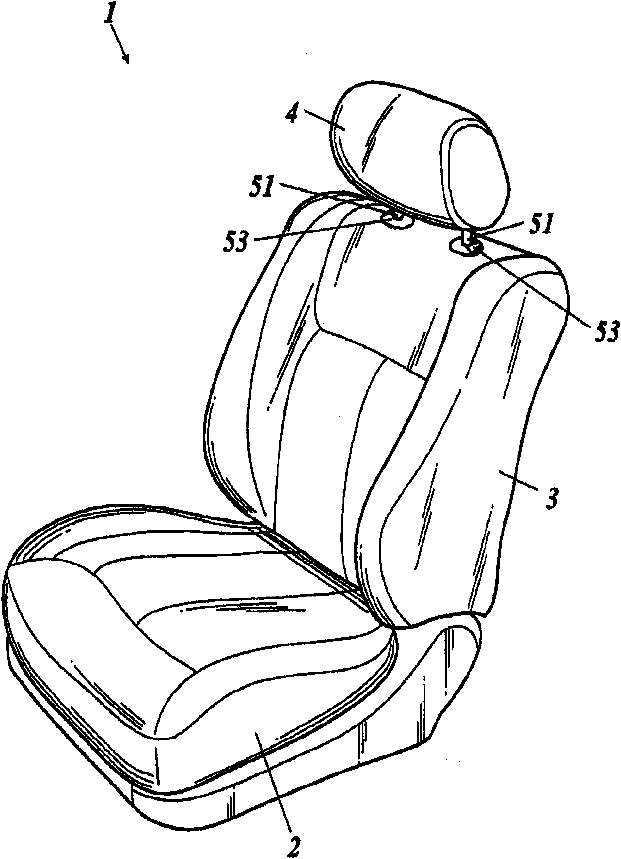
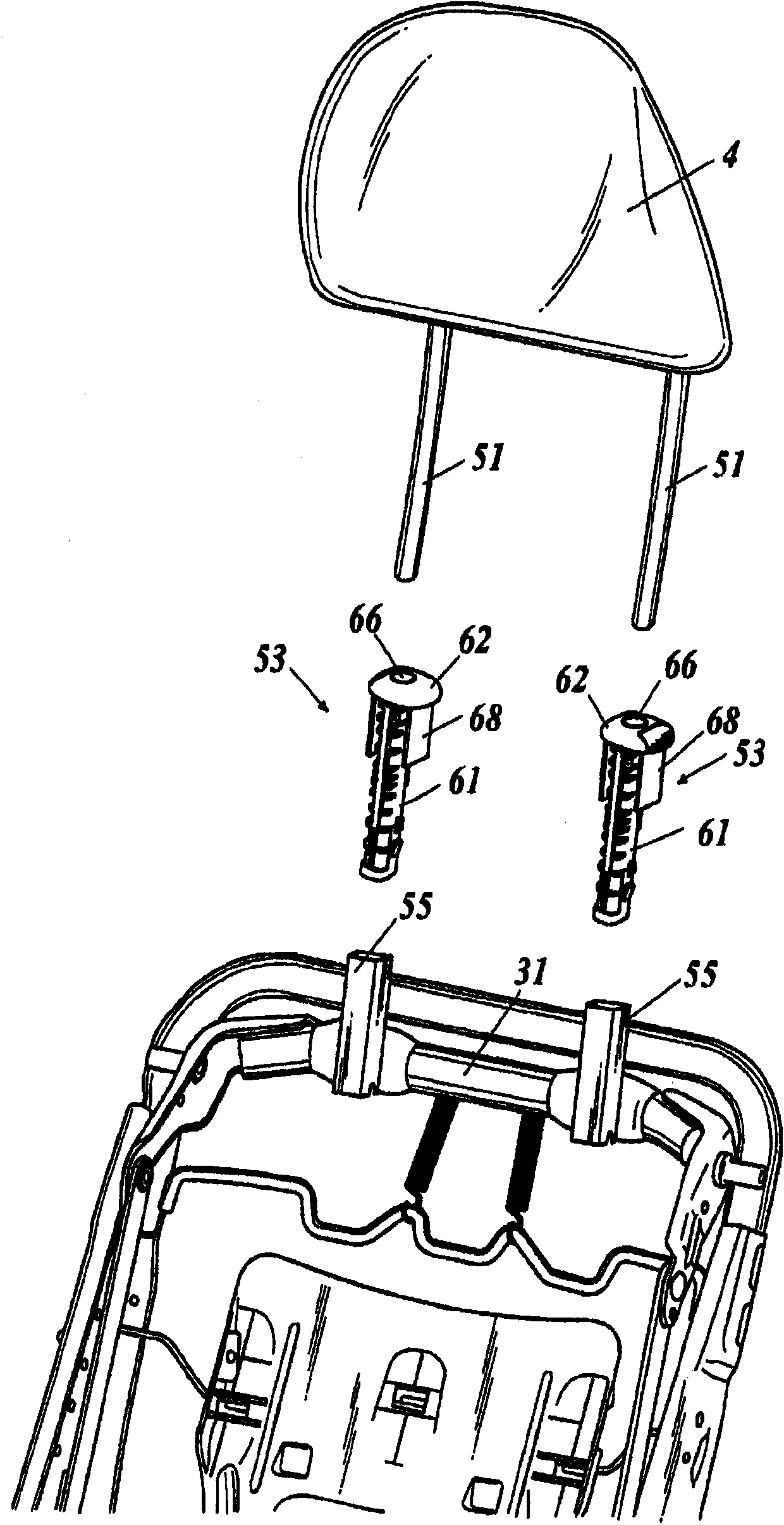
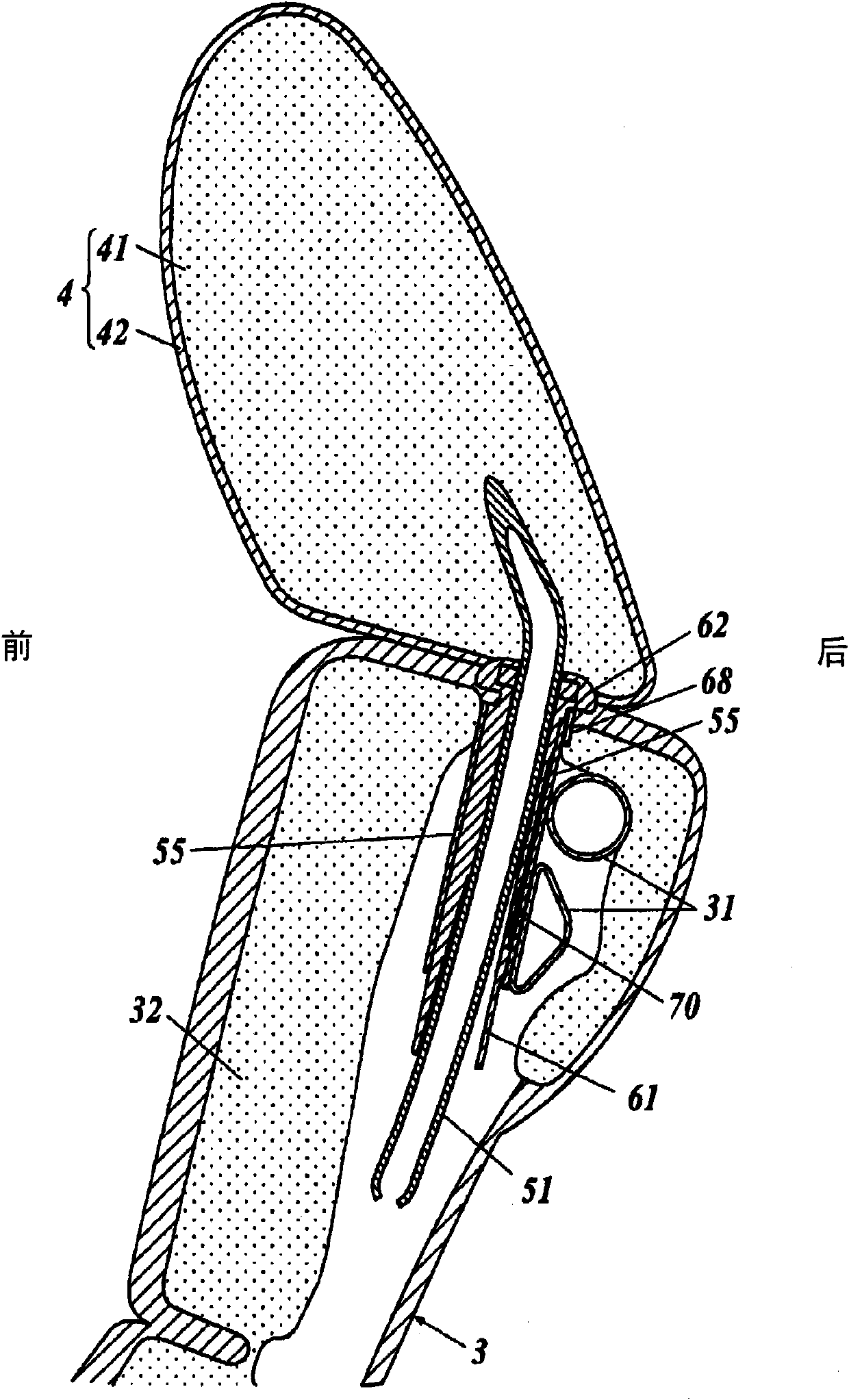
[0079] figure 1 It is a perspective view showing the vehicle seat 1 . figure 2 It is an exploded perspective view showing the headrest support structure of the vehicle seat 1 in disassembly. image 3 It is a longitudinal sectional view showing the upper portion of the backrest 3 of the vehicle seat 1 , the headrest 4 and its supporting structure.
[0080] As shown in these figures, a vehicle seat 1 includes a seat portion 2 , a backrest 3 connected to a rear end portion of the seat portion 2 , and a headrest 4 provided on an upper portion of the backrest 3 .
[0081] The seat 2 is connected to the vehicle floor through the front and rear position adjustment mechanism and the height adjustment mechanism, the front and rear positions of the seat 2 are adjusted by the position adjustment mechanism, and further, the height of the seat 2 is adjusted by the height adjustment mechanism. In addition, conventionally known mechanisms can be used as such a position adjustment mechanis...
no. 2 approach
[0133] Such as Figure 15 As shown, in addition to the joint 131 , there are also joints 131 a , 131 b between the protruding portion 101 and the protruding portion 102 .
[0134] Similarly, the connecting portions 132a, 132b are interposed between the protruding portion 102 and the protruding portion 103, the connecting portions 133a, 133b are interposed between the protruding portion 103 and the protruding portion 104, and the connecting portions 134a, 134b are interposed between the protruding portion 104 and the protruding portion. Between 105, connecting parts 135a, 135b are interposed between protruding part 105 and protruding part 106, connecting parts 136a, 136b are interposed between protruding part 106 and protruding part 107, and connecting parts 137a, 137b are interposed between protruding part 107 and protruding part 107. between the protrusions 108, the connecting parts 138a, 138b are interposed between the protruding part 108 and the protruding part 109, the con...
no. 3 approach
[0138] Such as Figure 16 As shown, the lateral width of the protrusions 105 - 108 arranged in the middle part of the cylindrical part 61 in the vertical direction is larger than that of the protrusions 101 - 104 arranged in the upper part of the cylindrical part 61 . The left-right width of the protrusions 105 - 108 arranged in the middle part of the cylindrical part 61 in the vertical direction is larger than the width of the left-right direction of the protrusions 109 - 111 arranged in the lower part of the cylindrical part 61 .
[0139] exist Figure 10 In the part indicated by γ, although a large load acts from the support 51 to the cylindrical part 61, in this part, the length of the left-right direction of the protrusions 105-108 is longer than that of the other protrusions 101-104, 109-111. Since the length in the direction is long, deformation of the cylindrical portion 61 can be effectively suppressed.
PUM
 Abstract
Description
Claims
Application Information
 - R&D
- Intellectual Property
- Life Sciences
- Materials
- Tech Scout
- Unparalleled Data Quality
- Higher Quality Content
- 60% Fewer Hallucinations
Browse by: Latest US Patents, China's latest patents, Technical Efficacy Thesaurus, Application Domain, Technology Topic, Popular Technical Reports.
© 2025 PatSnap. All rights reserved.Legal|Privacy policy|Modern Slavery Act Transparency Statement|Sitemap|About US| Contact US: help@patsnap.com


