Loading cam device and friction roller-type speed reducer

a technology of friction roller and cam device, which is applied in the direction of gearing, gearing details, hoisting equipment, etc., can solve the problems of excessive pressure on the surface of each traction part, difficulty in regulating the contact angle with high precision, and causing the following problems, so as to prevent the retainer from falling or axially rattling, and secure the strength and stiffness of the retainer. , the effect of preventing excessive stress

Active Publication Date: 2019-01-01
NSK LTD
View PDF21 Cites 3 Cited by
  • Summary
  • Abstract
  • Description
  • Claims
  • Application Information

AI Technical Summary

Benefits of technology

[0056]According to the loading cam device and the friction roller-type speed reducer of the present invention, it is possible to prevent the retainer, which is provided in the gap between the disc and the cam plate, from coming down or axially ratting, and to secure the strength and stiffness of the retainer, irrespective of the increase in the gap according to the increase in the pressing force. That is, the projections are provided at the plurality of positions in the circumferential direction on both axial side surfaces of the retainer, and the portions of one axial surfaces of the cam plate and the disc, which portions face the respective projections, are provided with the concave portions. Therefore, even when the gap between the cam plate and the disc increases, it is possible to bring each projection and each concave portion close to each other, so that it is possible to prevent the retainer from coming down or axially rattling. Also, the respective projections are formed at the plurality of positions on both axial side surfaces of the retainer, at which the phases in the circumferential direction are offset from the pockets. Therefore, it is possible to prevent the stress from being excessively concentrated on the portions at which the respective pockets are formed, so that it is possible to secure the strength and stiffness of the retainer.
[0057]Also, according to the friction roller-type speed reducer of the present invention, it is possible to secure the durability and to improve the transmission efficiency. That is, the axial pressing force which is to be generated by the loading cam device is a summed force of the force which is to be generated as each rolling element overrides each cam surface and the force which is to be generated as the hydraulic pressure is increased in the hydraulic chamber provided between the cam plate and the moveable sun roller element based on the centrifugal force to be generated as the input shaft rotates. Therefore, it is possible to increase the axial pressing force, which is to be generated by the loading cam device, as the rotation of the input shaft becomes faster. As a result, it is possible to make a traction coefficient of each traction part of the friction roller-type speed reducer smaller (i.e., the pressing force is made larger) as the peripheral speed of each traction part becomes faster.

Problems solved by technology

In the conventional structure as described above, it is difficult to regulate the contact angle with high precision.
For this reason, the axial pressing force generated by the loading cam devices 9, 9 becomes excessively large, so that the surface pressure of each traction part excessively increases.
However, even when the retainer is provided, following problems may be caused.
In contrast, if the pressing force is properly made when the peripheral speed v is low, the gross slip is likely to occur at each traction part when the peripheral speed v is high.

Method used


Image

  • Loading cam device and friction roller-type speed reducer
  • Loading cam device and friction roller-type speed reducer
  • Loading cam device and friction roller-type speed reducer

Examples


Embodiment Construction

[0080]

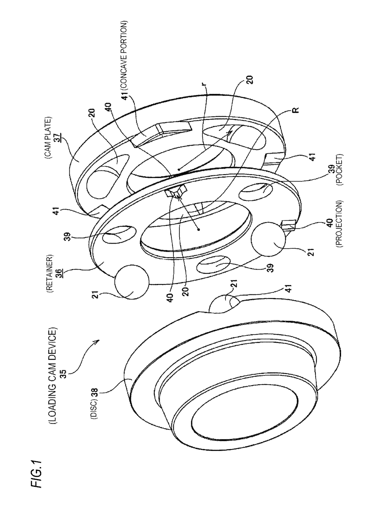
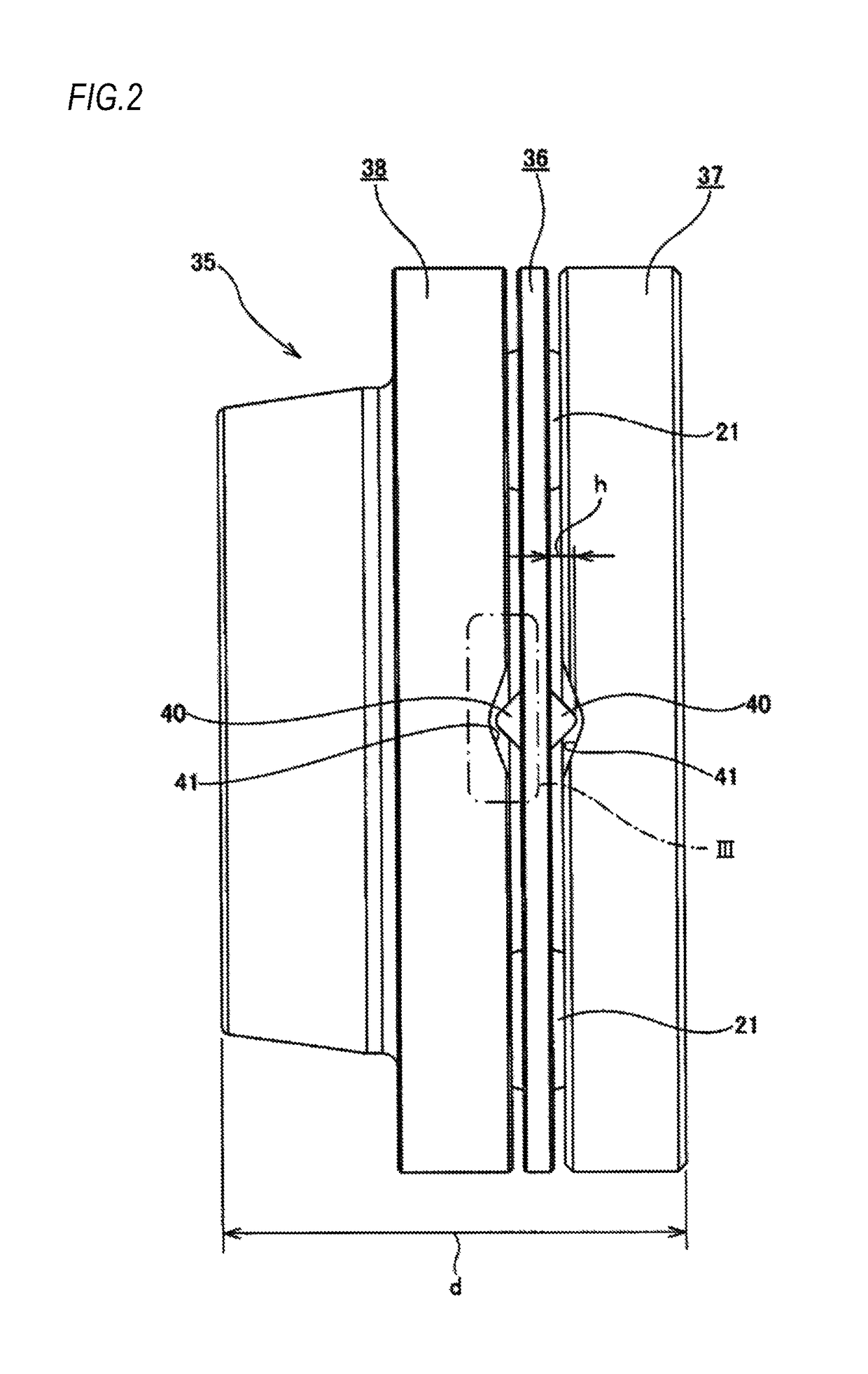
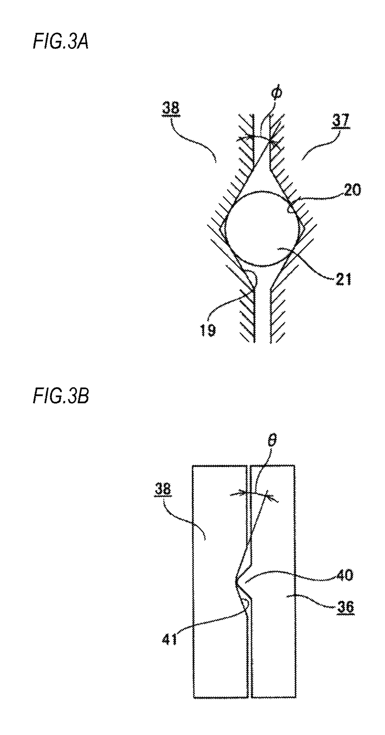
[0081]FIGS. 1 to 3 show a loading cam device in a friction roller-type speed reducer according to a first aspect. A feature of this aspect is a structure capable of preventing a retainer 36 incorporated in a loading cam device 35 from coming down or axially rattling and securing strength and stiffness of the retainer 36 even when an axial thickness of the loading cam device 35 increases as the loading cam device 35 operates. The structures and operations of the other parts are similar to the loading cam device incorporated in the conventional friction roller-type speed reducer shown in FIGS. 13 to 18. For this reason, the illustration and description of the equivalent parts will be omitted or simplified, and the feature of the first aspect will be mainly described in the below.

[0082]In the first aspect, the loading cam device 35 includes a rotary shaft (not shown), a cam plate 37, a disc (moveable sun roller element) 38, a plurality of (three, in the shown example) balls 21, 2...


PUM


Abstract

Projections protruding towards a cam plate and a disc are provided on both axial side surfaces of the retainer at a plurality of positions at which phases of the projections in the circumferential direction are offset from pockets. One axial direction surface of the cam plate and the disc are formed with concave portions at portions facing the respective projections. The concave portions have an axial depth deepest at a center portion thereof in the circumferential direction and becoming shallower towards both end portions thereof.

Description

TECHNICAL FIELD[0001]The present invention relates to a loading cam device and a friction roller-type speed reducer.BACKGROUND ART[0002]For example, Patent Documents 1 and 2 disclose using a friction roller-type speed reducer to reduce rotation of an output shaft of a small electric motor rotating at high speed and then to transmit the same to driving wheels such that efficiency of the electric motor as a driving source of an electric vehicle is improved to lengthen a mileage per one time charging. FIGS. 13 to 18 show a friction roller-type speed reducer disclosed in Patent Document 2.[0003]A friction roller-type speed reducer 1 is configured to rotationally drive a sun roller 3 by an input shaft 2 to transmit rotation of the sun roller 3 to an annular roller 5 via a plurality of intermediate rollers 4, 4, and to take out rotation of the annular roller 5 from an output shaft 6. The respective intermediate rollers 4, 4 are configured to only rotate on rotation axes 7, 7 provided at r...

Claims


Application Information

Patent Timeline
Patent Type & Authority Patents(United States)
IPC IPC(8): F16H15/50F16H57/08F16H63/06F16H63/30F16H25/18F16H55/56F16H13/08
CPCF16H15/50F16H13/08F16H25/186F16H57/08F16H63/065F16H63/3023F16H55/56F16H2057/087F16H13/06F16H13/14
Inventor YOSHIOKA, HIROYASUINOUE, EIJIIMANISHI, TAKASHIKISHIDA, HIROTAKA
Owner NSK LTD
Why Eureka
Try Eureka