Method for assembling a magnetic attachment mechanism

Active Publication Date: 2019-01-08
CORRELATED MAGNETICS RES LLC
View PDF106 Cites 23 Cited by
  • Summary
  • Abstract
  • Description
  • Claims
  • Application Information

AI Technical Summary

Benefits of technology

[0005]Briefly, the present invention pertains to a magnetic attachment system for attaching a first object to a second object. A first magnet structure is attached to the first object and a second magnet structure is attached to the second object. The first and second objects are attached by virtue of the magnetic attraction between the first magnet structure and second magnet structure. The magnet structures comprise magnetic elements arranged in accordance with patterns based on various codes. In one embodiment, the code has certain autocorrelation properties. In further embodiments the specific type of code is specified. In a further embodiment, an attachment and a release configuration may be achieved by a simple movement of the magnet structures.
[0006]In one embodiment, the system may include a panel having a magnetic mounting that utilizes a plurality of magnets in a magnet structure that allows high magnetic force when the panel is installed and the magnet structure is aligned while permitting removal using relatively light force applied to misalign the magnet structure to allow removal. In one embodiment, the magnet structure can provide precision positioning of the panel to a position on the order of the width of a single component magnet of the magnet structure. In another embodiment, the magnet structure may be misaligned for removal by a rotation of the magnet structure. In a further embodiment, the misalignment may be achieved by a lateral shift of the magnet structure. The invention may be adapted to a wide variety of panels including but not limited to doors, window coverings, storm coverings, seasonal covering panels, baby gates, white boards, and green house panels.
[0007]One embodiment employs multiple magnet structures based on multiple unique codes for unambiguous article orientation or selection, where more than one orientation or selection is possible. A further embodiment includes an adhesive backing for quick accurate initial installation. Embodiments are disclosed that require no tools for subsequent removal and installation after an initial installation of the panel. Alternatively, a tool or key may be required for removal to add a degree of difficulty or security to prevent tampering. A further embodiment includes a second coded magnet structure for coupling to a release mechanism providing a unique security code to prevent tampering.

Problems solved by technology

Alternatively, a tool or key may be required for removal to add a degree of difficulty or security to prevent tampering.

Method used


Image

  • Method for assembling a magnetic attachment mechanism
  • Method for assembling a magnetic attachment mechanism
  • Method for assembling a magnetic attachment mechanism

Examples


Embodiment Construction

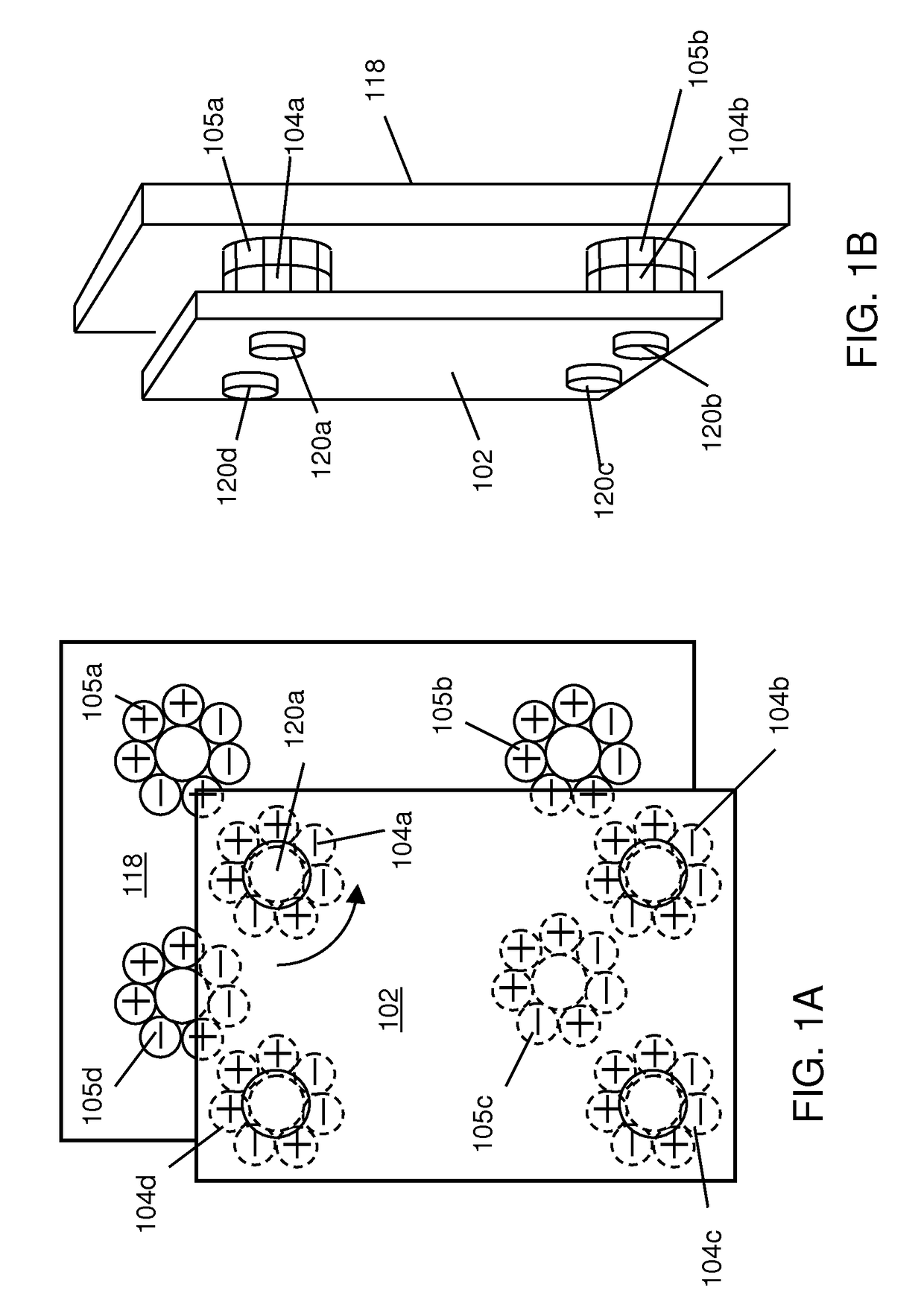
[0046]The present invention pertains to a magnetically attached panel which is held in place by a magnet structure comprising multiple magnets in an arrangement that generates a magnetization pattern that precisely positions the panel as if the strength of all of the magnets were concentrated in just one magnet location. One magnet structure is attached to the panel and is used with a complementary magnet structure that is attached to the support structure where the panel is to be mounted. Any number of magnets can be used as necessary to increase the strength of the holding force to securely hold the panel in place. For example, a holding force of 50 kilograms can be achieved with a magnet structure of 100 magnet pairs, each ½ cm square covering a square 5 centimeters on a side, and the magnet structure can position the panel to within a half centimeter. As a further capability of the invention, the magnet structure can be made to release with relatively light force compared with t...


PUM

PropertyMeasurementUnit
total magnetic forceaaaaaaaaaa
angleaaaaaaaaaa
anglesaaaaaaaaaa

Abstract

A magnetic attachment system for attaching a first object to a second object. A first magnet structure is attached to the first object and a second magnet structure is attached to the second object. The first and second objects are attached by virtue of the magnetic attraction between the first magnet structure and second magnet structure. The magnet structures comprise magnetic elements arranged in accordance with patterns based on various codes. In one embodiment, the code has certain autocorrelation properties. In further embodiments the specific type of code is specified. In a further embodiment, an attachment and a release configuration may be achieved by a simple movement of the magnet structures. In a further embodiment, the magnetic field structure may comprise multiple structures based on multiple codes.

Description

RELATED APPLICATIONS[0001]This application is a continuation of non-provisional application Ser. No. 15 / 188,760 titled “Magnetic Valve Assembly”, filed Jun. 21, 2016, by Fullerton et al.FIELD OF THE INVENTION[0002]The present invention pertains generally to the field of easily installed and removed panels for covering openings, supporting displays, and other purposes, and more particularly to panels that are expected to be repeatedly installed and removed.BACKGROUND[0003]There are numerous applications where panels are required to be installed on a temporary basis and then removed and potentially installed again for an indefinite number of installation and removal cycles, for example, storm windows, weather panels, hurricane boarding, construction barriers, white boards, sign boards and other panels. Such panels are typically installed with permanent fasteners, such as nails or screws that typically damage or mar the base structure, require tools for installation and removal of the ...

Claims


Application Information

Patent Timeline
Patent Type & Authority Patents(United States)
IPC IPC(8): H01F7/02F16K11/078B23P15/00E04F13/08F16K31/08
CPCB23P15/001E04F13/0883H01F7/021F16K31/088F16K11/0782B23P19/10
Inventor FULLERTON, LARRY W.ROBERTS, MARK D.
Owner CORRELATED MAGNETICS RES LLC
Why Eureka
Try Eureka