Self operatable ophthalmic device

a self-operating, ophthalmic device technology, applied in the field of optical instruments and devices, can solve the problems of affecting the test results of patients' fatigue, unable to underestimate the influence of patient fatigue, and difficulty in eye alignment for these devices, so as to improve the quality of the test results, remove motion artifacts, and facilitate image acquisition

Active Publication Date: 2019-01-15
HANGZHOU AIMU MEDITEC CO LTD
View PDF4 Cites 2 Cited by
  • Summary
  • Abstract
  • Description
  • Claims
  • Application Information

AI Technical Summary

Benefits of technology

[0010]The present invention describes a wearable, head mounted, ophthalmic device platform that enables the patient to align him or herself to the optical system of the device, and obtain quality test results without any medical staff or another person's assistance. As in sharp contrast to the traditional methods where the patients are only the passive subject of the exam, the present invention not only lets the patient participate in the whole process, but also allows the patient fully control the pace of the test.
[0011]The ophthalmic device according to the invention includes components such as a head mounted structure, like a goggle or a helmet, so that the patient's head position remains still relative to the ophthalmic device. Also, an “iris” camera system that records images or video streaming of the patient's iris / pupil during the exam. The patient's eyeball position and / or gaze direction are then analyzed based on the information obtained on the camera system. Two iris cameras, one for each eye can also be used. A display screen, such as the LCD or OLED displays used on cell phones, is included, to display fixation target and / or other information necessary to guide the patient to optimize the alignment, and complete the eye test. The display screen can be implemented as two discrete displays, one for each eye, or as one larger display with the screen split for each eye. In addition, a patient interface (PI) module for the patient to interact with the device is further implemented. The PI module can be integrated into the head mount structure, but preferably, it is a push button device operably connected to the device wirelessly, such as Bluetooth or with a cable, such as a USB connection. The PI module can have one or more buttons as necessary for the application. The PI module can also be an assembly of one or more sensors that collect the patient's various responses. The patient interface can also be through audio devices, such as a microphone and an earphone. Additional accessories can be added to the ophthalmic device, such as a modem for Internet connection to support communications with another person remotely. Furthermore, a cloud service connection can be implemented to store test results for remote access by the patient or other authorized persons. Biometric identification to enhance security and privacy of the patient data can also be achieved with the iris scans (using the device iris cameras) or fingerprints. And finally, an app, run on a second computer, tablet or smart phone, allows the medical professional to view the display screen on the ophthalmic device remotely, assign the test protocol, monitor the test progress, interact with the patient under test and review test results.
[0012]The present invention creates a much more comfortable test environment. The patient is completely immersed in the test device with only views to the test screen while no ambient light influences the test results. There is no need to block one eye when the other eye is under test. Both eyes are presented with a fixation target on the center of their own screen, which helps keep both eyes relaxed while fixing the gaze. Furthermore, no medical professional is needed to assist the patient to perform the exam. This is a significant advantage as it allows the exams to be taken at virtually anywhere besides the hospitals or clinics. Once the patient puts on the head mounted ophthalmic device comfortably, the device first aligns to the patient's eyes automatically. The patient can then decide to start whenever he or she is ready by pressing a button. Because the control is all on the patient, it is more likely that the patient has the best attention as the test starts and the retina image can be captured with no or much less unconscious blinks or saccades. Finally, the head mount or goggle-like structure allows the device to be held still related to the patient's head position during the test and creates a comfortable and immersive environment for the patient to focus on the exam and operate the device by him or herself. In fact, the patient can relax his or her head and take the exam while sitting, standing or laying down. The exam can also be paused temporarily and resumed at a later time.First Preferred Embodiment

Problems solved by technology

Eye alignment has remained a challenging problem for these devices.
However, even with today's computer assisted perimeter, it normally takes 5 to 10 minutes to complete the test on one eye.
The influence of a patient's fatigue on the test results cannot be underestimated and remains a major challenge for test reliability and accuracy.
The device used to capture a photograph of the fundus, often expensive and sophisticated, is called Fundus Camera.
To obtain high quality fundus photography can be very challenging.
Any misalignment of the patient's eyeball to the imaging optics may lead to unacceptable results.
Furthermore, the patient's unconscious head and eye movement can also happen at the moment when the medical staff presses the capture button, resulting in an unsuccessful attempt.
However, none of the fundus cameras in the market today can effectively alleviate the problem because the device operator could not anticipate the patient's possible reaction.
As a matter of fact, the quality of the fundus photography highly relies on the experience and skills of the device operator, which has hindered the device's usage, particularly in areas where the trained medical professionals are not easily accessible.
In fact, some instruments have to employ a technique so-called retina tracking to dynamically adjust the scanning spot following any head and / or eye movement at a cost of system complexity and expense.
Due to the scanning mechanism, OCT also requires a few seconds to complete the scan and consequently faces the same challenges as the SLO in regards to the patient head / eye movement.
All these factors make the traditional ophthalmic exams non-trivial even with a trained operator.

Method used


Image

  • Self operatable ophthalmic device
  • Self operatable ophthalmic device
  • Self operatable ophthalmic device

Examples


Embodiment Construction

[0031]While the present invention may be embodied in many different forms, designs or configurations, for the purpose of promoting an understanding of the principles of the invention, reference will be made to the embodiments illustrated in the drawings and specific language will be used to describe the same. It will nevertheless be understood that no limitation or restriction of the scope of the invention is thereby intended. Any alterations and further implementations of the principles of the invention as described herein are contemplated as would normally occur to one skilled in the art to which the invention relates.

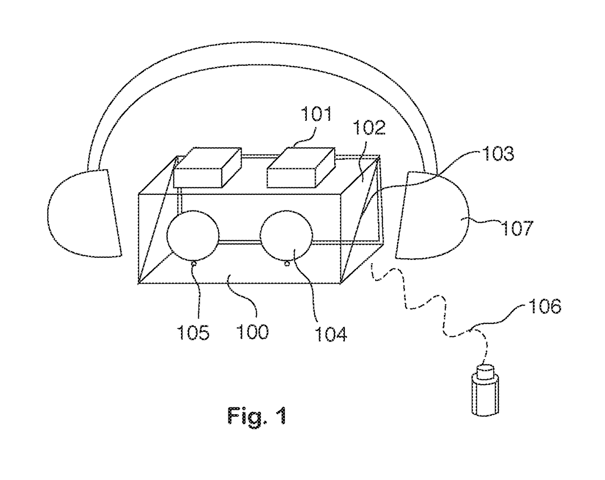
[0032]FIG. 1 is a perspective view illustration of the ophthalmic device platform according to the present invention. In this illustration, several key features inside the wearable ophthalmic device are shown including the head-mounted structure, on-axis cameras, ocular lenses, beam splitter, infrared illumination light emitting diodes (LEDs), display screen and pati...


PUM


Abstract

The invention provides a system for a patient to obtain quality eye tests results without other people's assistance. The system includes a wearable, head-mounted, ophthalmic device. With a head mounted structure, the patient's head position remains still relative to the ophthalmic device. One or more “iris” cameras and a display screen are used to help align the patient's eye on ocular lenses for optimal eye test results. The system includes a patient interface module that allows the patient to operate the device. Accessory features such as a microphone and earphones are used to communicate with a close by stander during and after the eye exam. Another key feature is a cloud service connection used to store test results for remote access by the patient or other authorized persons.

Description

[0001]This application claims priority to the U.S. provisional patent application Ser. No. 62 / 334,913, filed on May 11, 2016, the contents of which are incorporated by reference herein.FIELD OF THE INVENTION[0002]The present invention generally relates to optical instruments and devices used for detecting dysfunctions in human's vision and / or imaging the retina / cornea of the human eye. More particularly, the invention relates to a wearable, head mounted, ophthalmic device platform that enables the patient to align him or herself to the optical system of the device, and obtain quality test results without any medical personnel or another person's assistance.BACKGROUND OF THE INVENTION[0003]Ophthalmic devices such as a visual field analyzer, fundus camera, scanning laser ophthalmoscopy, optical coherence tomography (OCT) imager, and other instruments, have been traditionally operated in a clinical setting and by qualified medical professional. Eye alignment has remained a challenging ...

Claims


Application Information

Patent Timeline
Patent Type & Authority Patents(United States)
IPC IPC(8): A61B3/00A61B3/12A61B3/024A61B3/113A61B3/18
CPCA61B3/0041A61B3/0025A61B3/0033A61B3/18A61B3/113A61B3/12A61B3/024
Inventor LIU, QINGDICAI, MING
Owner HANGZHOU AIMU MEDITEC CO LTD
Why Eureka
Try Eureka