
System and method for temperature cycling

a technology of temperature cycling and system, applied in the direction of individual semiconductor device testing, measurement devices, instruments, etc., can solve the problems of increasing power consumption and heat production, increasing the size and power of the chip constantly, and inducing thermo-mechanical failure, etc., to achieve accelerated and economical testing

Active Publication Date: 2014-07-15
NVIDIA CORP
View PDF18 Cites 2 Cited by
  • Summary
  • Abstract
  • Description
  • Claims
  • Application Information

AI Technical Summary

Benefits of technology

This approach provides accelerated and economical testing of semiconductor devices under real-world-like conditions, effectively detecting thermo-mechanical failures and optimizing material compositions for longer product lifetime, while reducing testing time and costs.

Problems solved by technology

As a result, increasingly smaller and more powerful chips are constantly manufactured.
As smaller more advanced chips are made, the number of transistors increases resulting in increased power consumption and heat production.
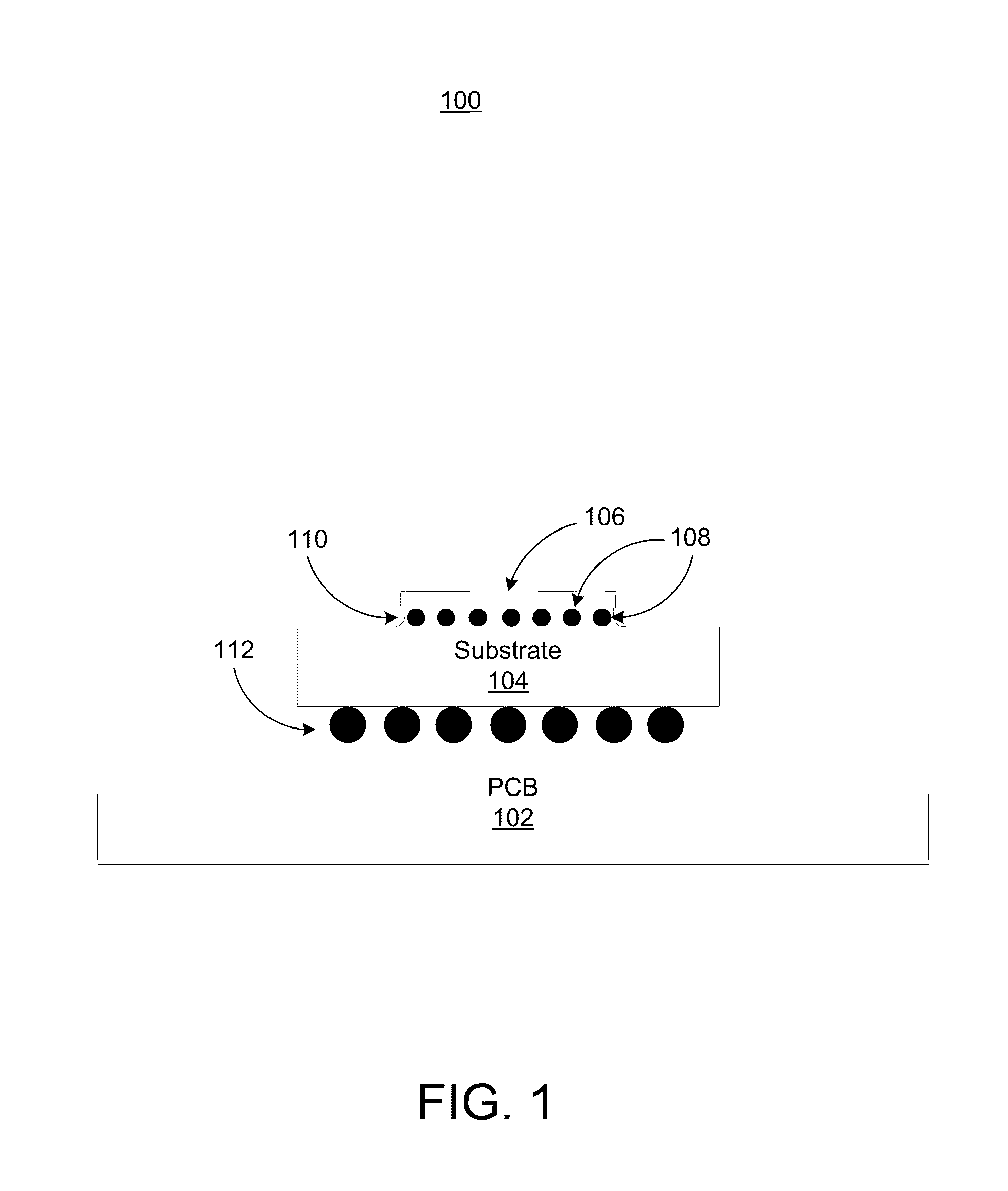
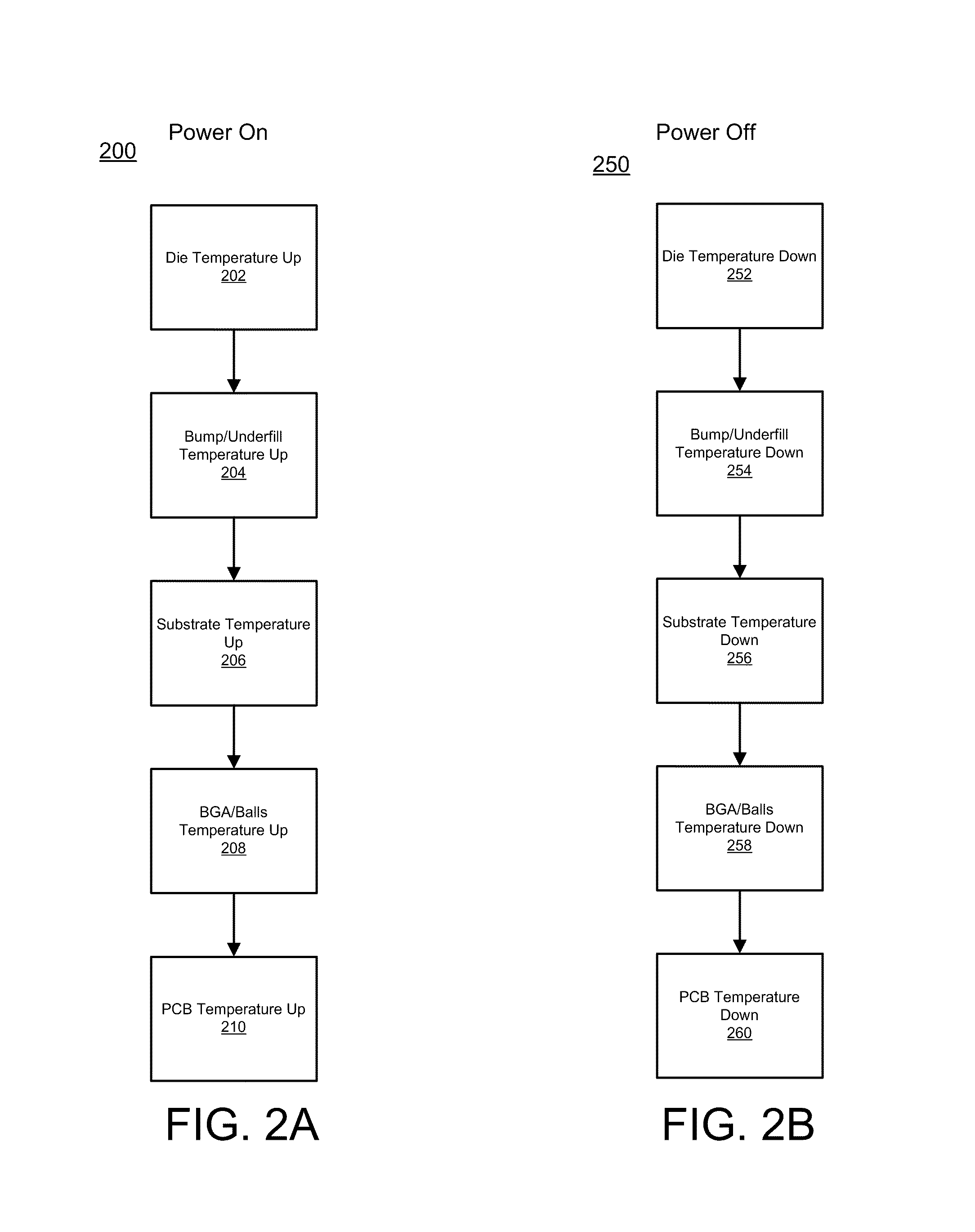
During semiconductor qualification, temperature cycling is done to simulate the temperature going up and down and thereby inducing thermo-mechanical failure.
As the temperature goes up and down, there is a thermal mismatch between different materials in a package.
Thus, at higher temperatures the substrate may expand more than the die unfortunately causing stress at the interface between the die and the substrate.
One of the problems with this kind of traditional temperature cycling is that it is isothermal because the temperature is driven by the ambient temperature and the chip remains unpowered.
Unfortunately, thermo-mechanical stresses from actual operating conditions are quite different from the ambient controlled isothermal nature of ATC.
This creates non-uniform heating and non-uniform temperature distribution in the package.
Thus, when ATC testing is used the results do not sufficiently reflect real world conditions.
That is, ATC is not able to simulate an actual user's power on / standby / off cycling conditions due to the nature of ATC being an isothermal ambient temperature controlled test method.
However, this method does not provide consistent and accurate temperature profiles across testing devices as thermal behavior of each device can be different.
The testing temperature range is also limited as this method relies on self heating and ambient temperature cooling.
However, this method also does not provide consistent and accurate temperature profiles across testing devices as thermal behavior of each device can be different.
The testing temperature range and number of cycles within a given time period are also limited as this method relies on self heating and ambient temperature cooling.
Further, this method involves high costs and time in building systems, developing special software, and maintenance.

Method used


Image

  • System and method for temperature cycling
  • System and method for temperature cycling
  • System and method for temperature cycling

Examples


Embodiment Construction

[0022]Reference will now be made in detail to the preferred embodiments of the present invention, examples of which are illustrated in the accompanying drawings. While the invention will be described in conjunction with the preferred embodiments, it will be understood that they are not intended to limit the invention to these embodiments. On the contrary, the invention is intended to cover alternatives, modifications and equivalents, which may be included within the spirit and scope of the invention as defined by the appended claims. Furthermore, in the following detailed description of embodiments of the present invention, numerous specific details are set forth in order to provide a thorough understanding of the present invention. However, it will be recognized by one of ordinary skill in the art that the present invention may be practiced without these specific details. In other instances, well-known methods, procedures, components, and circuits have not been described in detail ...


PUM


Abstract

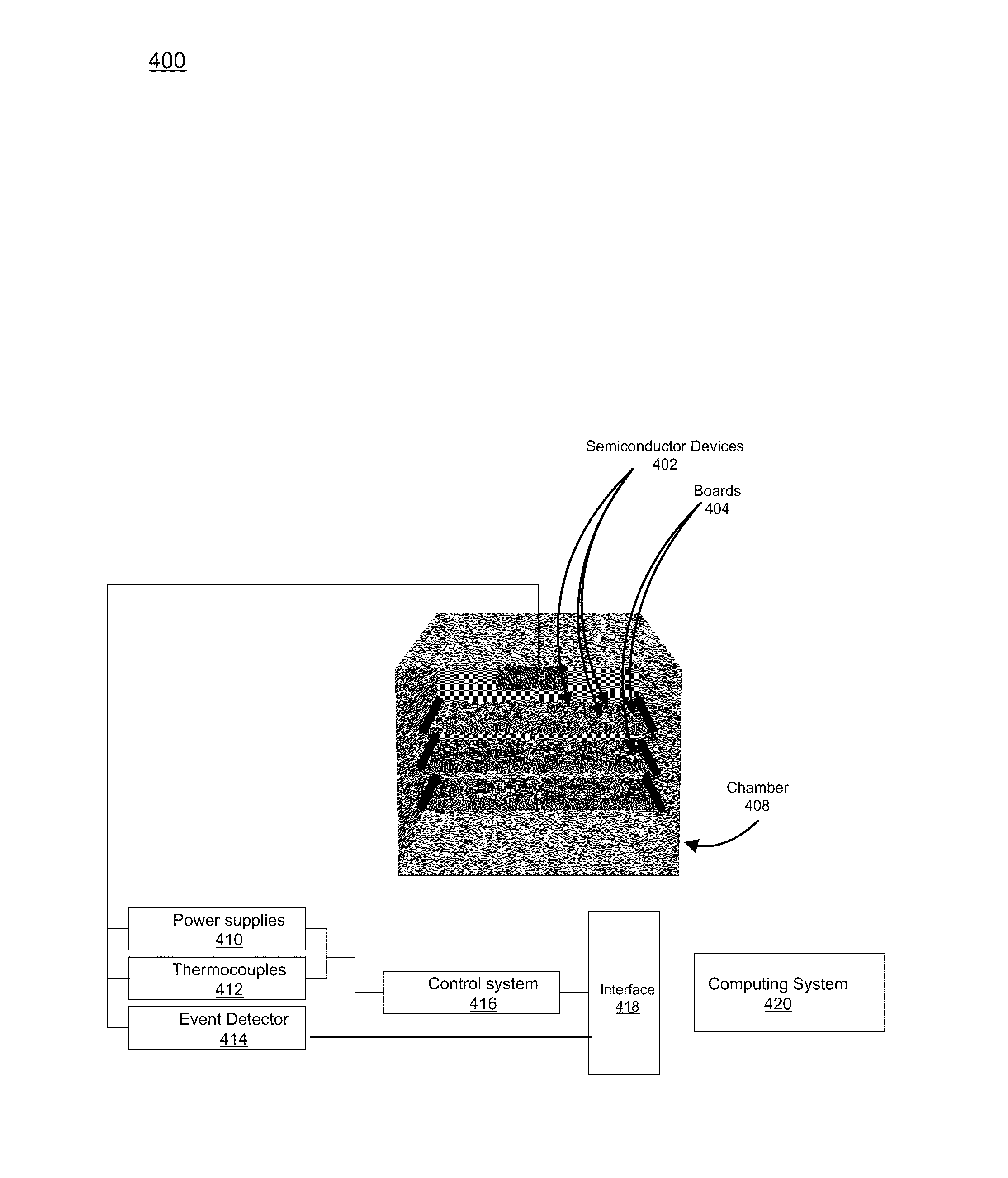
A system and method for non-isothermal temperature cycling (also called Conduction Temperature Cycling) of a semiconductor device. The method includes inserting a semiconductor device into a testing chamber and thermally coupling the semiconductor device to a heating and cooling element via a vacuum holding component. The method further includes heating and cooling a die portion of the semiconductor device with the heating and cooling element and testing the semiconductor device for component failure caused by thermo-mechanical stress induced by the non-isothermal temperature cycling. In one embodiment, the heating and cooling comprises non-isothermal temperature cycling.

Description

FIELD OF THE INVENTION[0001]Embodiments of the present invention are generally related to temperature cycling systems and device testing.BACKGROUND OF THE INVENTION[0002]As computer systems have advanced, processing power and capabilities have increased both terms of general processing and more specialized processing such as graphics processing and chipsets. As a result, increasingly smaller and more powerful chips are constantly manufactured. As smaller more advanced chips are made, the number of transistors increases resulting in increased power consumption and heat production. This has made chip cooling important but has also made the packaging materials important as repeated heating and cooling during typical usage induces stresses on packages thereby effecting the life of the chip.[0003]Before a chip package is finalized, the design is tested to ensure it is able to withstand stresses induced by repeated heating and cooling during usage. During semiconductor qualification, temp...

Claims


Application Information

Patent Timeline
Patent Type & Authority Patents(United States)
IPC IPC(8): G01R31/26G01R31/28H01L21/67
CPCG01R31/26G01R31/2851H01L21/67115G11C29/06G11C29/56016G11C2029/5602
Inventor SHIN, KYUNG MOMCMULLEN, THOMASKIM, DONG WOOK
Owner NVIDIA CORP
Learn More