
Multi-node synchronous on-site test method

a multi-node, on-site test technology, applied in power supply testing, power measurement by digital technique, electrical equipment, etc., can solve the problems of large safety, stability and reliable operation of power systems, and the inability to test monitoring and control systems in large regions with multiple nodes, so as to improve the reliability level of systems

Active Publication Date: 2017-10-10
ELECTRIC POWER RES INST STATE GRID JIANGXI ELECTRIC POWER CO
View PDF6 Cites 0 Cited by
  • Summary
  • Abstract
  • Description
  • Claims
  • Application Information

AI Technical Summary

Benefits of technology

This patent describes a new method for testing equipment and systems in power systems. The method uses GPS time to synchronize multiple testing devices in different locations. The testing devices are controlled by a central control center, resulting in a unified output of simulation signals. This allows for the testing of various dynamic monitoring and control systems, ensuring the proper functioning of the systems. Compared to traditional in situ testing methods, this method is faster and more comprehensive, and can help improve the reliability of power systems. The technology is ideal for testing the function of intelligent control systems in power grids, which are essential for safe and steady operation of large power grids.

Problems solved by technology

Interconnection of power grids in large regions, especially interconnection of “Sanhua” extra-high voltage synchronous large power grid, brings great challenges for safety, stability and reliable operation of power system.
At present, traditional equipment test method within power transmission and transformation station of power system and booster station of power plant is generally in situ test, i.e., connecting standard device to equipment under test in situ for voltage and current boosting, and then comparing and calculating the standard value and measured value to obtain test results; however, if such in situ test method cannot be expanded to synchronous simulation test between multiple transformer stations and booster stations of power plants, test of monitoring and control systems in large regions with multiple nodes cannot be carried out.

Method used


Image

  • Multi-node synchronous on-site test method
  • Multi-node synchronous on-site test method
  • Multi-node synchronous on-site test method

Examples


Embodiment Construction

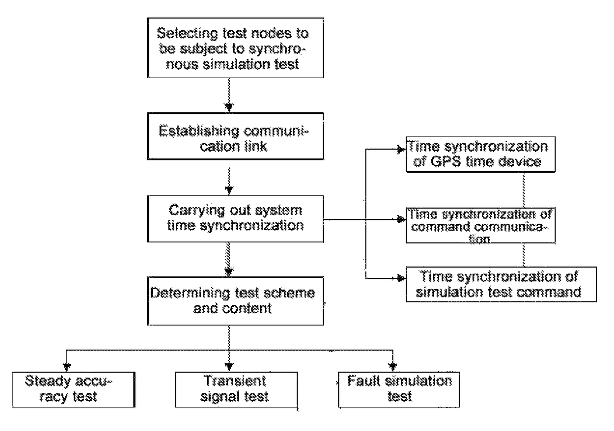
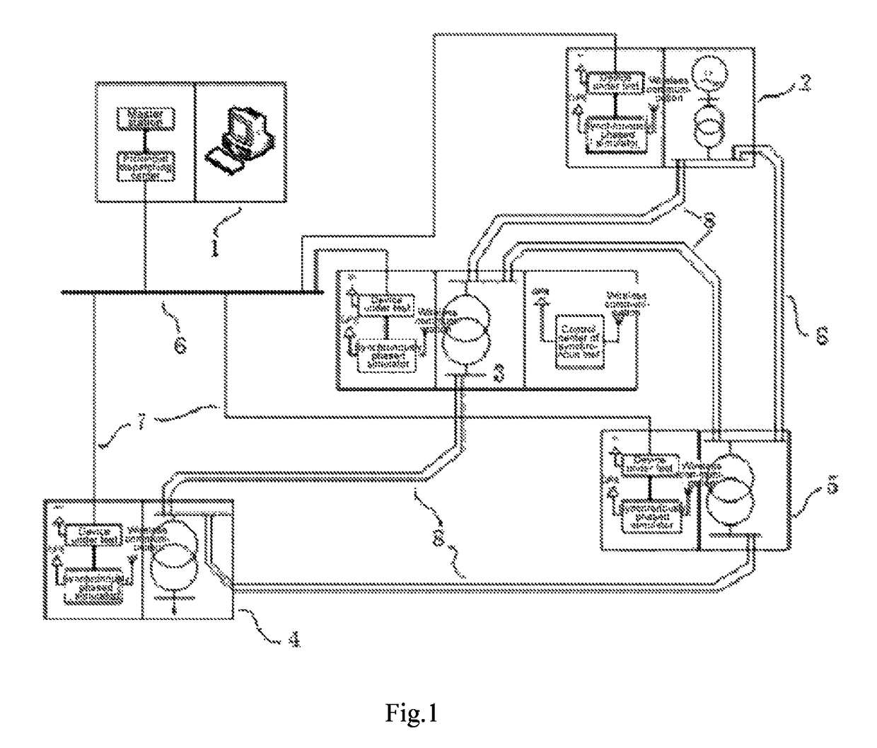
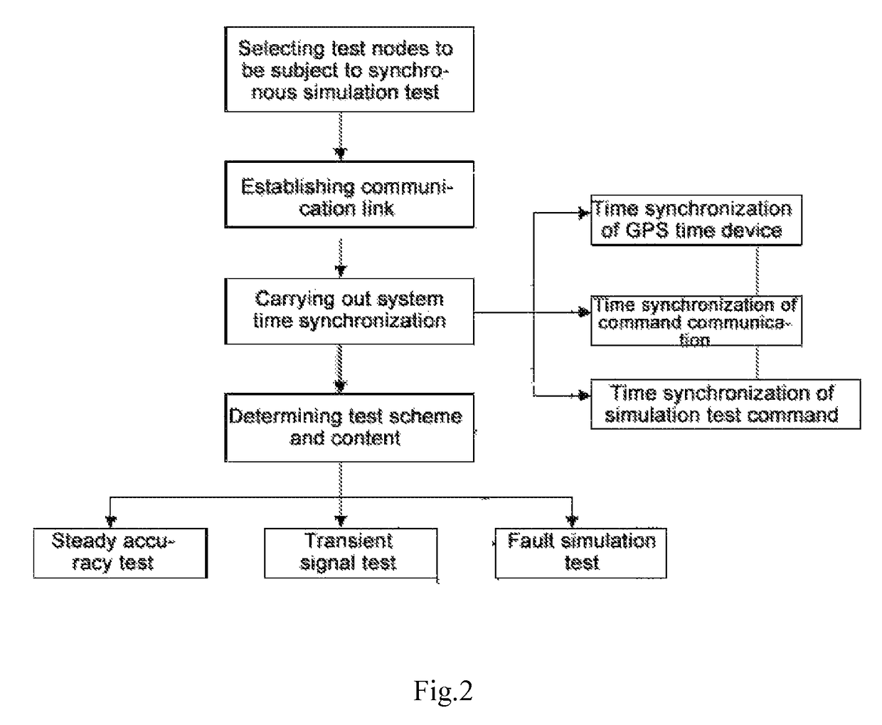
[0026]Description of the preferred embodiment of the present invention is shown in FIGS. 1 and 2.

(1) Firstly Select Test Nodes to be Subject to Synchronous Simulation Test

[0027]In the present embodiment, an important node of power supply side, power plant 2, and three nodes of power grid side connected to power plant: transformer station A3, B4 and C5 are selected. The control center of synchronous test is located in the center node, transformer station A.

[0028]Work permit must be applied for from the provincial dispatching center 1 before carrying out site test after selecting test nodes to prevent occurrence of incorrect operation caused by simulation test. The rule of electric work tickets must be followed in case of working in electric field, and test personnel must be very familiar with actual wiring condition of devices on site before carrying out multi-node synchronous simulation test, otherwise occurrence of security incidents is easy to be caused. Since multi-node synchrono...


PUM


Abstract

A multi-node synchronous on-site test method, the method comprising: using GPS time as time reference, and conducting synchronous on-site tests on the devices to be tested and systems distributed at different places at an appointed time; controlling the synchronous phase control simulation devices distributed at multiple nodes via a synchronous test control center; within a uniform time section, synchronously outputting secondary side AC simulation signals, and simulating various actual operating conditions, thus achieving the detection of the monitoring and control performances of various dynamic monitoring and control systems, and ensuring the normal functions of the systems. The method of the present invention is able to conduct multi-node dynamic simulation test with synchronized GPS time, and achieves the detection of large-area multi-node monitoring and control systems. The present invention is suitable for the test of a wide area measurement system (WAMS) function, the simulation test of a damping control function, the simulation test of transiently stable state analysis and control functions, the simulation test of voltage stabilization and control functions, the simulation test of an islanding control function, the simulation test of wide area protection system functions and the like.

Description

TECHNICAL FIELD[0001]The present invention relates to a multi-node synchronous simulation test method, belonging to technical field of power system measurement.BACKGROUND ARTS[0002]Interconnection of power grids in large regions, especially interconnection of “Sanhua” extra-high voltage synchronous large power grid, brings great challenges for safety, stability and reliable operation of power system. It is very important to increase test frequency of various dynamic monitoring and control systems, make the monitoring system functional, and build and improve intelligent monitoring, scheduling and control systems. At present, traditional equipment test method within power transmission and transformation station of power system and booster station of power plant is generally in situ test, i.e., connecting standard device to equipment under test in situ for voltage and current boosting, and then comparing and calculating the standard value and measured value to obtain test results; howe...

Claims


Application Information

Patent Timeline
Patent Type & Authority Patents(United States)
IPC IPC(8): G01R31/40H02J13/00G01R21/133
CPCG01R31/40H02J13/0079G01R21/133H02J13/00028H02J13/00034
Inventor PEI, MAOLINSUN, PINGZHANG, CHUNQIANGLIU, JIANHU, HAIMEIZHU, MING
Owner ELECTRIC POWER RES INST STATE GRID JIANGXI ELECTRIC POWER CO
Learn More