Cleaning device

a cleaning device and jet flow technology, applied in the direction of cleaning using liquids, applications, transportation and packaging, etc., can solve the problems of residues that need to be removed, quality defects of manufactured pharmaceuticals, and damage to the apparatus, so as to achieve efficient cleaning, efficient removal of dirt, and high cleaning capacity

Active Publication Date: 2019-01-15
SHARP KK
View PDF11 Cites 2 Cited by
  • Summary
  • Abstract
  • Description
  • Claims
  • Application Information

AI Technical Summary

Benefits of technology

[0045]According to the invention, the cleaning device is provided with the cleaning tank, the cleaning fluid retention portion which retains the cleaning fluid for cleaning the object, the cleaning fluid discharge portion which is connected to the cleaning fluid retention portion, and discharges the cleaning fluid retained in the cleaning fluid retention portion in a pressured state, and a pipe of which one end portion is connected to the cleaning fluid discharge portion, and the cleaning portion which ejects the cleaning fluid, in the cleaning tank. The cleaning portion may be installed so as to be immersed in the cleaning fluid. The cleaning portion includes a first flow passage which is connected to the other end portion of the pipe, and to which the cleaning fluid which is pressure-fed by the cleaning fluid discharge portion is supplied, a second flow passage which is continued to a downstream end of the first flow passage, and of which a flow passage cross-sectional area is smaller than that of the first flow passage, a third flow passage which is continued to a downstream end of the second flow passage, and of which a flow passage cross-sectional area becomes gradually larger as being separated from the second flow passage, and an accommodating space which is continued to a downstream end of the third flow passage, and is capable of accommodating the object.
[0046]In the cleaning device configured as described above, when the object is disposed in the accommodating space, and the cleaning fluid which is in a pressured state is supplied from the cleaning fluid discharge portion to the first flow passage in the cleaning portion, the cleaning fluid flowing through the second flow passage is ejected to the accommodating space via the third flow passage. With this, it is possible to efficiently impart the jet flow caused by the cleaning fluid to the outer surface of the object which is disposed in the accommodating space, thereby realizing high cleaning capability. Therefore, even though the object is a component having a pillar or bar-like structure, among components constituting a pharmaceutical manufacturing machine, or a medical instrument having a pillar or bar-like structure, such as a pestle of a tablet machine, an endoscopic surgical instrument, and a radio knife, it is possible to efficiently remove dirt such as residues of a pharmaceutical and an adversely changed body fluid which are stuck to the object.
[0047]In addition, according to the invention, the size of the accommodating space is sufficient for accommodating the entirety of the object. Therefore, among the components constituting the pharmaceutical manufacturing machine, in the component having the pillar or bar-like structure or the medical instrument having the pillar or bar-like structure, it is possible to efficiently impart the jet flow caused by the cleaning fluid to not only the tip end portion on one side in the longitudinal direction but also the side surface portion thereof, thereby cleaning the entirety of the object with strong physical force. Accordingly, it is possible to efficiently remove the residues of the pharmaceutical, the oil stain, the blood stain, and the like which are stuck to the side surface portion without cleaning unevenness.
[0048]In addition, according to the invention, the first flow passage is formed into a right cylinder shape, the second flow passage is formed into a right cylinder shape having the outer diameter which is smaller than the outer diameter of the first flow passage, and the third flow passage is formed into a truncated cone shape having the outer diameter at the upstream end thereof which is equivalent to the outer diameter of the second flow passage, and the outer diameter at the downstream end which is larger than the outer diameter of the second flow passage. That is, the cleaning portion has a so-called venturi tube structure. With such a venturi tube structure, some of the pressure energy of the fluid is replaced with speed energy, and it is possible to eject the cleaning fluid having the flow rate accelerated in the second flow passage of which the flow passage cross-sectional area is reduced, to the accommodating space via the third flow passage. As a result, as described above, even though the object is, among components constituting a pharmaceutical manufacturing machine, a component having a pillar or bar-like structure or a medical instrument having a pillar or bar-like structure, it is possible to efficiently remove dirt such as the residues of the pharmaceutical and the adversely changed body fluid which are stuck to the object.
[0049]Further, according to the invention, the accommodating space is formed into a right cylinder shape having an outer diameter which is the same or substantially the same as the outer diameter of the third flow passage at the downstream end. With this, in the ejecting hole which is formed in the third flow passage, it is possible to guide the physical force which works in a bus line direction into the accommodating space without the force being lost in the cleaning tank. As a result, as described above, even though the object is, among components constituting a pharmaceutical manufacturing machine, a component having a pillar or bar-like structure or a medical instrument having a pillar or bar-like structure, it is possible to efficiently remove dirt such as the residues of the pharmaceutical and the adversely changed body fluid which are stuck to the object.
[0050]Further, according to the invention, the cleaning portion is provided with a projecting portion which is projected inwardly in an inner periphery portion which forms the accommodating space. With this, it is possible to guide the physical force which works in the direction parallel with the side surface of the object which is guided in the accommodating space to the direction perpendicular to the side surface of the object by the projecting portion. As a result, as described above, even though the object is, among components constituting a pharmaceutical manufacturing machine, a component having a pillar or bar-like structure or a medical instrument having a pillar or bar-like structure, it is possible to efficiently remove dirt such as residues of the pharmaceutical, the oil stain, the grease stain, and an adversely changed body fluid which are particularly stuck to the side surface of the object.

Problems solved by technology

Deposits which are formed of the residues of the pharmaceutical causes damage to an apparatus and a quality defect of the manufactured pharmaceutical, and thus are required to be removed.
In addition, similarly in a component of a grinder which is used to improve elution of a poorly water soluble drug in the manufacturing of the pharmaceutical, there is a problem that the residues of the pharmaceutical are deposited, and thus the deposited residues are required to be removed.
In other to remove the residues of the pharmaceutical which are stuck to the component constituting the pharmaceutical manufacturing machine such as the tablet machine and the grinder, the component is cleaned with hands by using a brush; however, such a cleaning operation is complicated and troublesome.
Further, when a body fluid such as blood during the surgery is stuck to a medical instrument used in surgery, if the medical instrument is a radio knife or the like of which the temperature becomes high, the body fluid which is stuck to the medical instrument is burned and fixed due to the heat of the medical instrument.
In addition, even in a case of a high reactive chemical, for example, even when the body fluid comes in contact with acid, the body fluid is adversely changed, and fixed to the medical instrument.
In this way, it is not possible to remove the body fluid which is fixed to the medical instrument with a washer disinfector using a general cleaning agent.
The cleaning guidelines 2010 by Japanese Society of Medical Instrumentation states “the body fluid which is burned at a tip end of bipolar coagulation forceps cannot be removed by automatic cleaning”, and in the actual medical field, for example, the medical instrument with stain is immersed into an alkali cleaning agent for a while, and then is cleaned with hands by using a brush; however, there is a problem in that such a cleaning operation is complicated and troublesome.

Method used


Image

  • Cleaning device
  • Cleaning device
  • Cleaning device

Examples


first embodiment

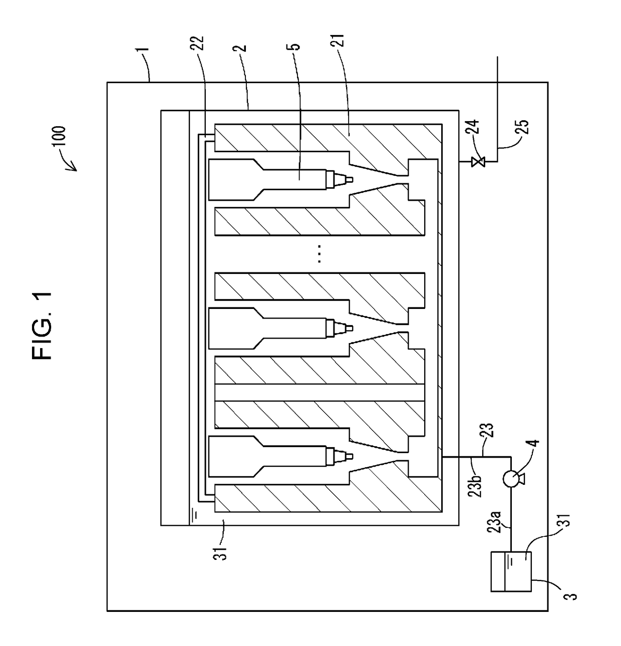
[0072]FIG. 1 is a diagram schematically illustrating a configuration of a cleaning device 100 according to a first embodiment of the invention. It is possible to realize a cleaning method of the invention by using the cleaning device 100.

[0073]The cleaning device 100 is an apparatus which cleans an object 5 such as a component for constituting a pharmaceutical manufacturing machine and a medical instrument, and an apparatus for removing dirt such as residues of a pharmaceutical (powder), oil, and grease which are stuck to the component for constituting the pharmaceutical manufacturing machine, and a body fluid which is burned and stuck to the medical instrument by a physical force and a chemical force.

[0074]Examples of the object 5 such as a component constituting a pharmaceutical manufacturing machine which performs a cleaning treatment in the cleaning device 100 include a mortar, a pestle, and a rotary board of a tablet machine which compression-molds a tablet for a pharmaceutical...

second embodiment

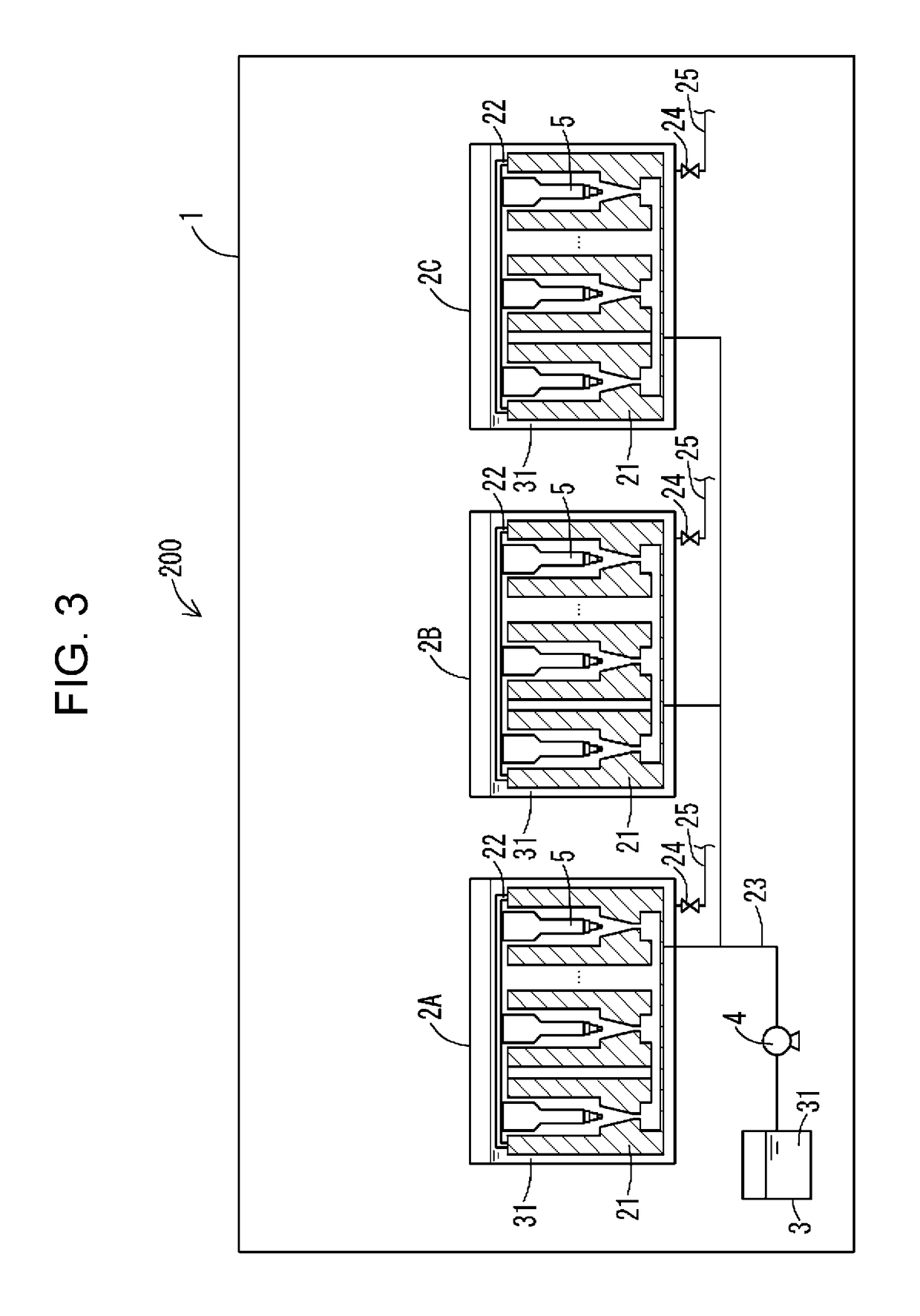
[0101]FIG. 3 is a diagram schematically illustrating a configuration of a cleaning device 200 according to a second embodiment of the invention. A configuration of the cleaning device 200 is similar to that of the cleaning device 100 in the first embodiment, and thus corresponding constituent elements are given the same reference numerals, and the description thereof will be omitted.

[0102]In the cleaning device 200, a plurality of cleaning tanks 2A, 2B, and 2C which are formed in the same way as the cleaning tank 2 provided in the cleaning device 100 as described above are arranged in parallel. Each of the cleaning tanks 2A, 2B, and 2C is provided with a plurality of the cleaning nozzle members 21 similarly in the cleaning tank 2. FIG. 3 illustrates three cleaning tanks 2A, 2B, and 2C which are arranged in parallel, but the number of the cleaning tanks is not limited thereto, for example, two cleaning tanks, or four or more of cleaning tanks may be arranged in parallel.

[0103]Each of...

third embodiment

[0105]FIG. 4 is a diagram schematically illustrating a configuration of a cleaning device 300 according to a third embodiment of the invention. The configuration of the cleaning device 300 is similar to that of the cleaning device 100 in the first embodiment, and thus corresponding constituent elements are given the same reference numerals, and the description thereof will be omitted.

[0106]The cleaning device 300 is configured to clean the object 5 by further imparting the ultrasonic vibration as a physical force to the above-described cleaning device 100.

[0107]The cleaning device 300 is formed of the cleaning tank 2 which is provided in the cleaning device 100 in the first embodiment, and an ultrasonic wave generating unit 301. The ultrasonic wave generating unit 301 is installed by coming in contact with the cleaning nozzle member 21, and generates ultrasonic waves when the object 5 is cleaned with the jet flow caused by the cleaning fluid 31.

[0108]Accordingly, in the cleaning dev...


PUM

PropertyMeasurementUnit
flow rateaaaaaaaaaa
pHaaaaaaaaaa
inner diameteraaaaaaaaaa

Abstract

A cleaning device (100) according to the present invention is constituted by including in a cleaning nozzle member (21) provided inside a cleaning tank (2): a large pipe diameter part (211) that supplies a cleaning fluid (31) pressure-fed from a retention tank (3); a small pipe diameter part (212) that increases the speed of a flow rate for the cleaning fluid (31) flowing in the large pipe diameter part; a conical pipe diameter part (213) that generates a fluid that includes minute bubbles by cavitation; and a guide pipe diameter part (214) for accommodating an object (5) to be cleaned. The cleaning fluid (31) is ejected to the entirety of the object (5).

Description

TECHNICAL FIELD[0001]The present invention relates to a cleaning device for removing dirt sticking to an object such as a component and a medical instrument which form a pharmaceutical manufacturing machine.BACKGROUND ART[0002]In the related art, a pharmaceutical tablet is compression-molded by adding a lubricant, or the like to granulated pharmaceuticals, or a material which is obtained by adding and evenly mixing an excipient, a binder, a disintegrant, and other materials into the granulated pharmaceuticals. As a compression molding apparatus in the pharmaceutical manufacturing machine, for example, a tablet machine including a rotary board on which a plurality of mortars are disposed at a peripheral edge, and an upper pestle and a lower pestle which are disposed in a vertically slidable manner in the vertical direction with respect to the rotary board, and the like are known. The tablet machine is configured such that a mortar hole, in which a bottom of the mortar hole is formed ...

Claims


Application Information

Patent Timeline
Patent Type & Authority Patents(United States)
IPC IPC(8): A61B90/70B08B3/12B08B3/10B08B3/08B08B3/02B05B7/04B01F5/04B01F3/04B08B5/00
CPCB01F5/0426B01F5/0428B05B7/0483B08B3/10B08B3/102B08B3/12B08B5/00B08B3/08B08B3/02B01F3/04503B01F5/043B01F2005/0438A61B2090/701B01F23/2323B01F25/31242B01F25/31241B01F25/31243B01F25/31252
Inventor FUKUMOTO, SHOHEIYAMAMOTO, HIROAKITAMURA, KOHICHINAKAMURA, KOHICHI
Owner SHARP KK
Why Eureka
Try Eureka