Cleaning apparatus for heat exchanger and polishing apparatus

a technology of heat exchanger and cleaning apparatus, which is applied in the direction of lighting and heating apparatus, flush cleaning, lapping machines, etc., can solve the problems of reducing the reliability of semiconductor devices, affecting the yield of semiconductor devices, and forming scratches on the surface of wafers

Active Publication Date: 2022-07-12
EBARA CORP
View PDF6 Cites 0 Cited by
  • Summary
  • Abstract
  • Description
  • Claims
  • Application Information

AI Technical Summary

Benefits of technology

[0008]Therefore, there is provided a cleaning apparatus capable of effectively removing dirt attached to a bottom surface of a heat exchanger. Further, there is provided a polishing apparatus including such a cleaning apparatus.
[0029]According to the above-described embodiments, the cleaning liquid is ejected from the cleaning liquid nozzle to the bottom of the heat exchanger moved to the retreat position, or the bottom of the heat exchanger moved to the retreat position is immersed in the cleaning tank in which the cleaning liquid is stored. As a result, dirt is prevented from firmly adhering to the bottom surface of the heat exchanger, and dirt can be effectively removed from the bottom surface of the heat exchanger.

Problems solved by technology

When dirt falls down from the heat exchanger during polishing of the wafer, and is caught between the polishing pad and the wafer, scratches are formed on the surface of the wafer.
The scratches can be a cause of defects that lower a reliability of the semiconductor devices.
In other words, Scratches can cause a decrease in the yield of semiconductor devices.
Further, in recent years, there has been a demand for shortening a cleaning time of the heat exchanger to improve a throughput of the polishing apparatus, and therefore, it has become difficult to set aside enough ejecting time of the cleaning liquid for removing dirt attached to the heat exchanger.
Further, a downsizing of the polishing apparatus is also required, and thus, in some cases, the cleaning liquid ejected from the cleaning liquid nozzles cannot be effectively applied to the bottom surface of the heat exchanger where the most dirt adheres (i.e., the surface that is in contact with or close to the surface of the polishing pad).

Method used


Image

  • Cleaning apparatus for heat exchanger and polishing apparatus
  • Cleaning apparatus for heat exchanger and polishing apparatus
  • Cleaning apparatus for heat exchanger and polishing apparatus

Examples


Embodiment Construction

[0070]Embodiments will now be described with reference to the drawings.

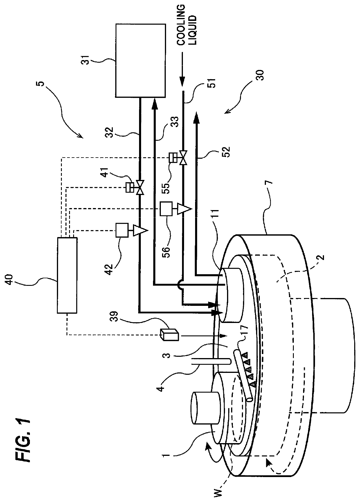
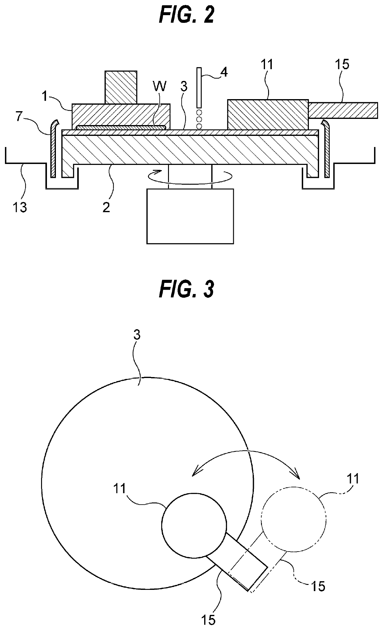
[0071]FIG. 1 is a schematic view showing a polishing apparatus according to an embodiment. FIG. 2 is schematic cross-sectional view of a main part of the polishing apparatus shown in FIG. 1. The polishing apparatus shown in FIGS. 1 and 2 includes a polishing head 1 for holding and rotating a wafer W which is an example of a substrate, a polishing table 2 that supports a polishing pad 3, a polishing-liquid supply nozzle 4 for supplying a polishing liquid (e.g. a slurry) onto a surface of the polishing pad 3, and a pad-temperature regulating apparatus 5 for regulating a surface temperature of the polishing pad 3. The surface (upper surface) 3a of the polishing pad 3 provides a polishing surface for polishing the wafer W.

[0072]The polishing head 1 is vertically movable, and is rotatable about its axis in a direction indicated by arrow. The wafer W is held on a lower surface of the polishing head 1 by, for example, v...


PUM


Abstract

A cleaning apparatus capable of effectively removing dirt attached to a bottom surface of a heat exchanger, is disclosed. The cleaning apparatus cleans the heat exchanger for regulating a surface temperature of a polishing pad. This cleaning apparatus includes: a moving mechanism configured to move the heat exchanger between a temperature-regulating position in which the heat exchanger can exchange heat with the polishing pad, and a retreat position in which the heat exchanger is separated from a surface of the polishing pad; and a cleaning mechanism configured to clean a bottom surface of the heat exchanger moved to the retreat position The retreat position is located on a side of the polishing pad. The cleaning mechanism includes at least one cleaning nozzle for ejecting a cleaning liquid to the bottom surface of the heat exchanger, or a cleaning tank in which the bottom surface of the heat exchanger can be immersed.

Description

CROSS REFERENCE TO RELATED APPLICATION[0001]This document claims priority to Japanese Patent Application Number 2019-067930 filed Mar. 29, 2019, the entire contents of which are hereby incorporated by reference.BACKGROUND[0002]A CMP (Chemical Mechanical Polishing) apparatus is used in a process of polishing a surface of a wafer in the manufacturing of a semiconductor device. The CMP apparatus is configured to hold and rotate the wafer with a polishing head, and press the wafer against a polishing pad on a rotating polishing table to polish the surface of the wafer. During polishing, a polishing liquid (or slurry) is supplied onto the polishing pad, so that the surface of the wafer is planarized by the chemical action of the polishing liquid and the mechanical action of abrasive grains contained in the polishing liquid.[0003]A polishing rate of the wafer depends not only on a polishing load on the wafer pressed against the polishing pad, but also on a surface temperature of the polis...

Claims


Application Information

Patent Timeline
Patent Type & Authority Patents(United States)
IPC IPC(8): B24B5/00B24B37/20F28G3/02
CPCB24B37/20F28G3/02F28G13/00F28G15/00B24B37/04B24B37/34B24B57/02H01L21/67017H01L21/67051H01L21/67092H01L21/67103F28G3/04H01L21/6704H01L21/67046H01L21/68714H01L21/6838H01L21/67219F28G15/04F28G1/166F28G9/00F28G1/02F28G15/02B24B37/015H01L21/30625H01L21/304
Inventor MOTOSHIMA, YASUYUKIMARUYAMA, TORUKAMIKI, KEISUKEUOZUMI, SHUJI
Owner EBARA CORP
Why Eureka
Try Eureka