Vertically brushing electric toothbrush

An electric toothbrush, vertical brush technology, applied in dentistry, cleaning teeth, medical science and other directions, can solve problems such as difficult to achieve tooth protection, and achieve the effect of removing dirt

Inactive Publication Date: 2007-11-28
TRULY ELECTRONICS MFG
View PDF8 Cites 0 Cited by
  • Summary
  • Abstract
  • Description
  • Claims
  • Application Information

AI Technical Summary

Problems solved by technology

And the scientific way of brushing teeth should be that the bristles brush along the direction between the teeth, that is, vertical brushing. Therefore, the brushing method of the existing electric toothbrush does not fully meet the requirements of scientific toothbrushing, and it is difficult to achieve tooth protection and effectively remove dirt in the teeth spaces. the goal of

Method used


Image

  • Vertically brushing electric toothbrush
  • Vertically brushing electric toothbrush
  • Vertically brushing electric toothbrush

Examples


Embodiment 1

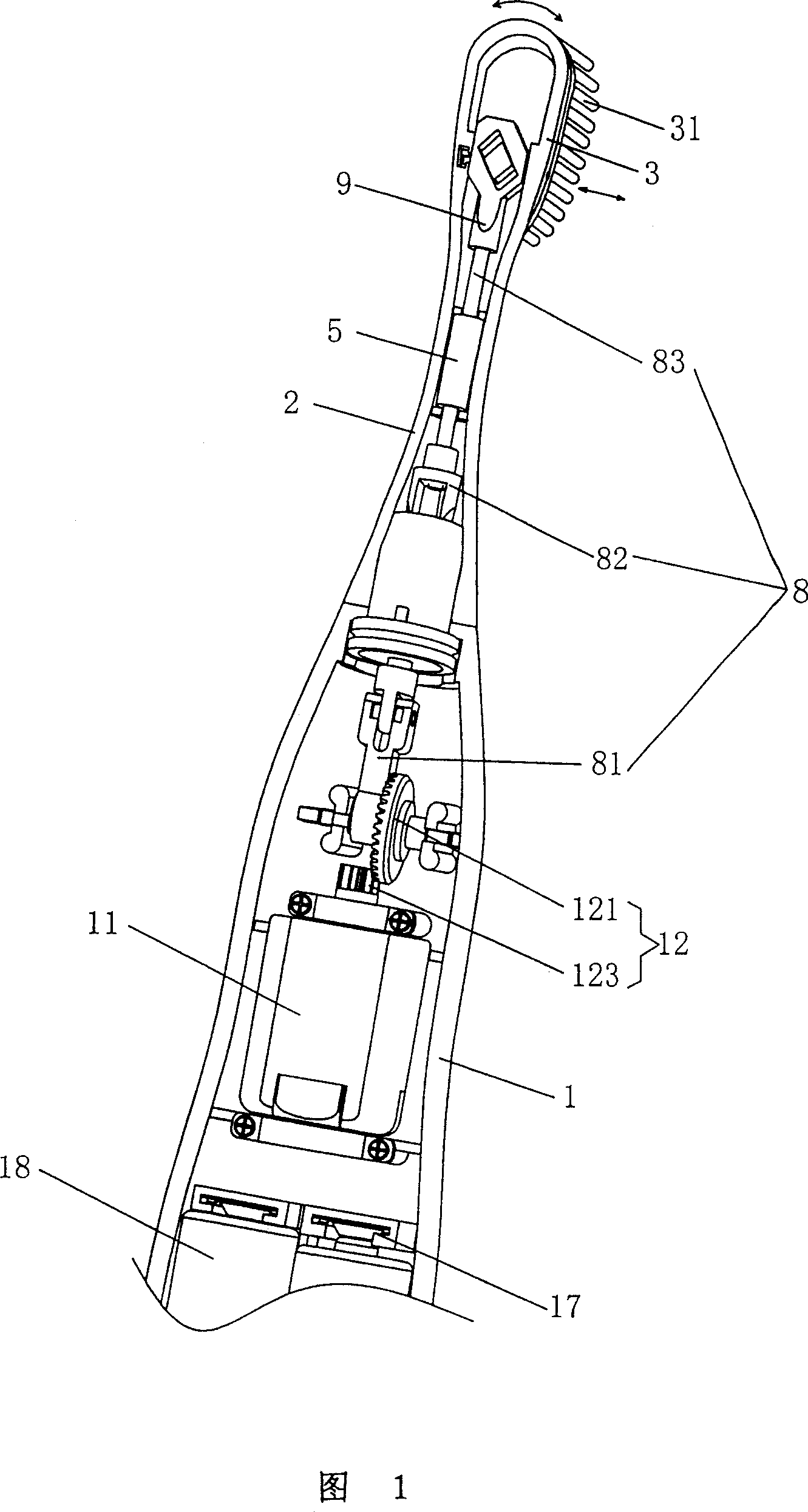
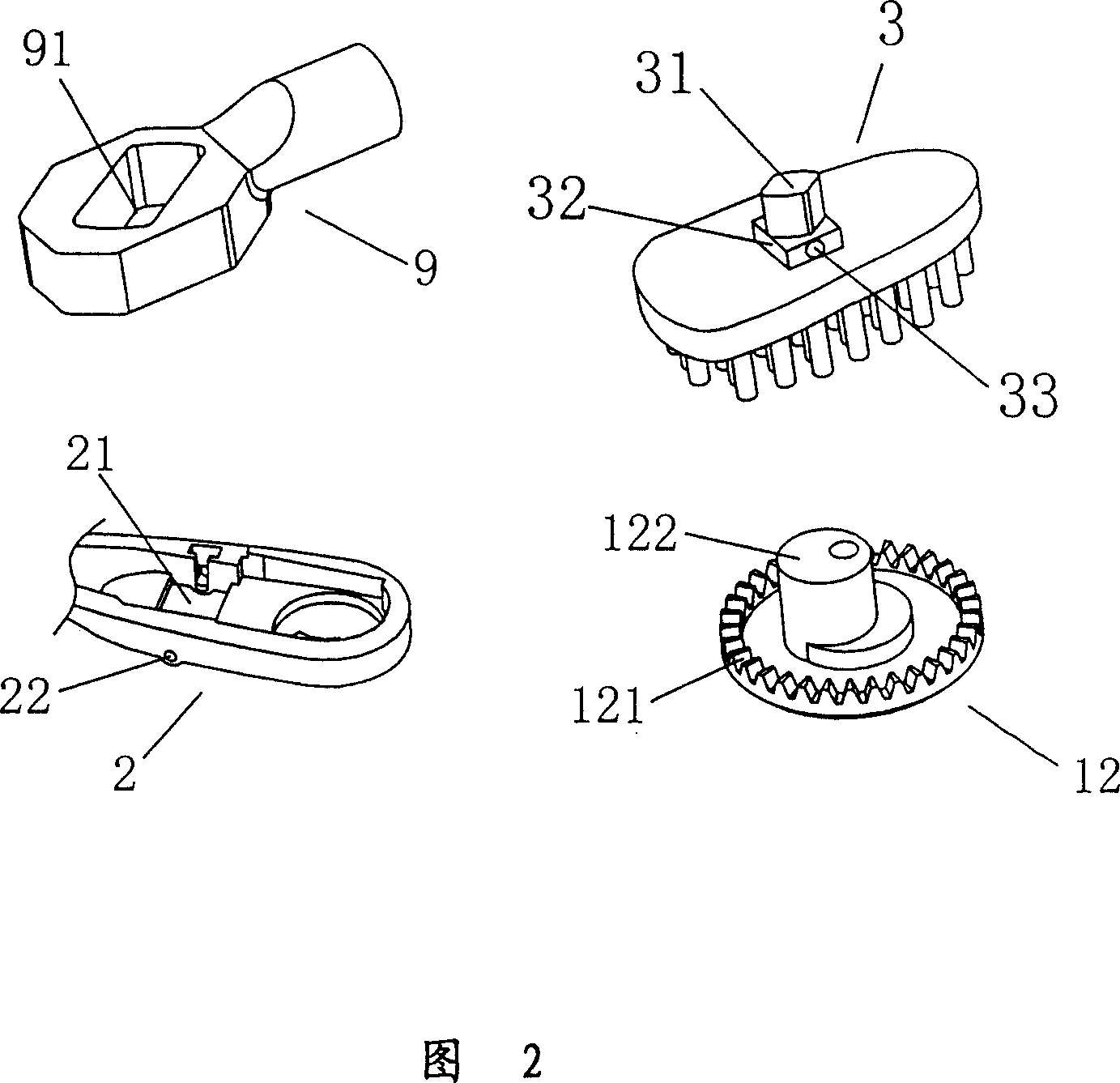
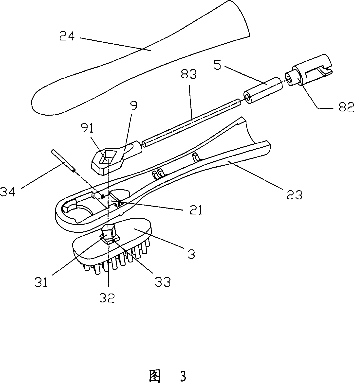
[0019] As shown in Figure 1, the vertical brush type electric toothbrush of the present invention comprises: the motor 11 that is placed in toothbrush body 1 inner cavity and the speed change gear set 12 that is driven by motor 11, the toothbrush handle 2 that is installed on toothbrush body 1 top and is arranged on The toothbrush head 3 in the front section of the toothbrush handle 2 is movably connected with the toothbrush handle 2 , and the front of the toothbrush head 3 is fixed with toothbrush hairs 31 . Described transmission gear set 12 comprises the driving gear 123 that is fixed on the power output shaft of motor 11 and the driven gear 121, is provided with eccentric shaft 122 (Fig. The rotary motion of the speed change gear set 12 is converted into the reciprocating linear motion of the toothbrush head driving pull rod 9 . The connecting rod device 8 includes a connecting rod 81, a connecting head 82 and a pull rod shaft 83 which are sequentially connected from back ...

Embodiment 2

[0026]The difference between this embodiment and the first embodiment is that a circular rotating brush head 4 is added at the front end of the toothbrush handle 2 to improve brushing efficiency. As shown in Figures 5 and 6, the rotating brush head 4 has a central axis hole 41 The central axis hole 41 is rotatably matched with the hanging shaft 27 fixed on the toothbrush handle 2, a driving shaft 42 is vertically protruded on the left side of the central axis hole 41, and a section of arc-shaped neck is arranged on the right side of the central axis hole 41. The arc-shaped neck and the back of the rotating brush head 4 form an anti-slip groove 44. Correspondingly, the front end of the toothbrush handle 2 has a circular through hole 25, and a fan-shaped convex key 26 is protruded on its right side wall. The brush head 4 is suspended on the toothbrush handle 2 and can rotate within a certain angle around the toothbrush handle 2 hanging shaft 27 . A pull piece 92 is extended on ...


PUM


Abstract

The vertically brushing electric toothbrush includes toothbrush handle, toothbrush head, speed varying gear set, link rod unit and toothbrush head driving pull rod. The speed varying gear set is provided with eccentric shaft to convert rotation motion into linear reciprocation of the toothbrush head driving pull rod; the toothbrush head has squared column in the back to penetrate the hole in the toothbrush handle for loose fitting with the toothbrush head driving pull rod; and one guide shaft perpendicular to the axis of the toothbrush handle is fixed onto the toothbrush handle via the guide hole to make the toothbrush head reciprocate linearly along the guide shaft. The electric toothbrush of the present invention has the bristles brush vertically along the tooth gap to eliminate dirt.

Description

technical field [0001] This invention relates to powered cleaning or polishing devices, and more particularly to electric toothbrushes for everyday use. Background technique [0002] Most of its toothbrush heads of existing electric toothbrushes adopt the mode of rotating brushing, as disclosed technical scheme of Chinese patent CN 2412546, CN 2080343, they all utilize rotating toothbrush heads to clean teeth. There is also an electric toothbrush (CN 2154025Y) that adopts a swinging scrubbing method, which adopts a swing bar to stir the toothbrush head to swing, and the bristles swing back and forth with an arc track to achieve the effect of cleaning teeth. Although the electric toothbrushes disclosed in U.S. Patent No. 8,778,474 and US 5,504,958 have adopted a crankshaft mechanism and a single row of bristles to swing, each row of toothbrush heads is rotatably fixed on an axis, so the single row of bristles is also curved in the shape of an arc. Orbital oscillating to clea...

Claims


Application Information

Patent Timeline
Patent Type & Authority Patents(China)
IPC IPC(8): A61C17/34
Inventor 黄邦俊
Owner TRULY ELECTRONICS MFG
Why Eureka
Try Eureka