

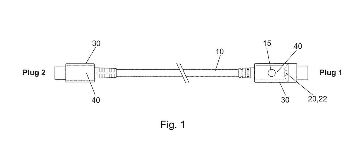
Illuminated USB type C power adapter
a power adapter and usb type technology, applied in the direction of electrical equipment, coupling device connections, two-part coupling devices, etc., can solve the problems of wasting power, difficult to align for interconnection, and difficulty in interconnecting the female interface of the male cable connector to the female interface of the electronic devi
- Summary
- Abstract
- Description
- Claims
- Application Information
AI Technical Summary
Benefits of technology
Problems solved by technology
Method used
Image

Examples
Embodiment Construction
[0022]The inventors have recognized that a cable with a USB-C connection interface cannot utilize the Vbus conductor previously relied upon to energize an interconnection area illuminating LED to guide interconnection in dark environments, because the USB-C connection interface specifies that the Vbus conductor is not energized until the connection interface has already been interconnected and data negotiation to identify the correct power level for the connected electronic device has been completed across the interconnection. That is, according to the USB-C specification, the Vbus conductor is unpowered until the interconnection operation desired to be illuminated has already been completed, so a conventional illuminated connection interface is inoperable where the connection interface is USB-C.
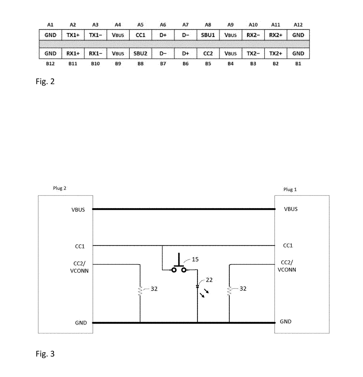
[0023]Details of the USB-C Technical Specification “Universal Serial Bus Revision 3.2”, hereby incorporated by reference in the entirety, may be found via the USB Implementers Forum, Inc. of...
PUM
 Abstract
Description
Claims
Application Information