
Illuminated interface cable

a technology of interface cables and illuminated cables, which is applied in the direction of lighting and heating apparatus, coupling device connections, lighting support devices, etc., can solve the problems of wasting power, difficult to align interconnection, and difficulty in interconnection of male cable connectors to female interfaces of electronic devices,

Inactive Publication Date: 2014-05-22
XENTRIS WIRELESS
View PDF7 Cites 10 Cited by
  • Summary
  • Abstract
  • Description
  • Claims
  • Application Information

AI Technical Summary

Benefits of technology

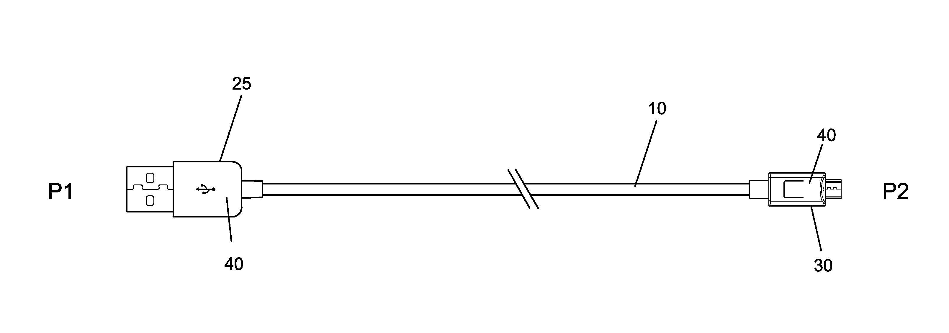
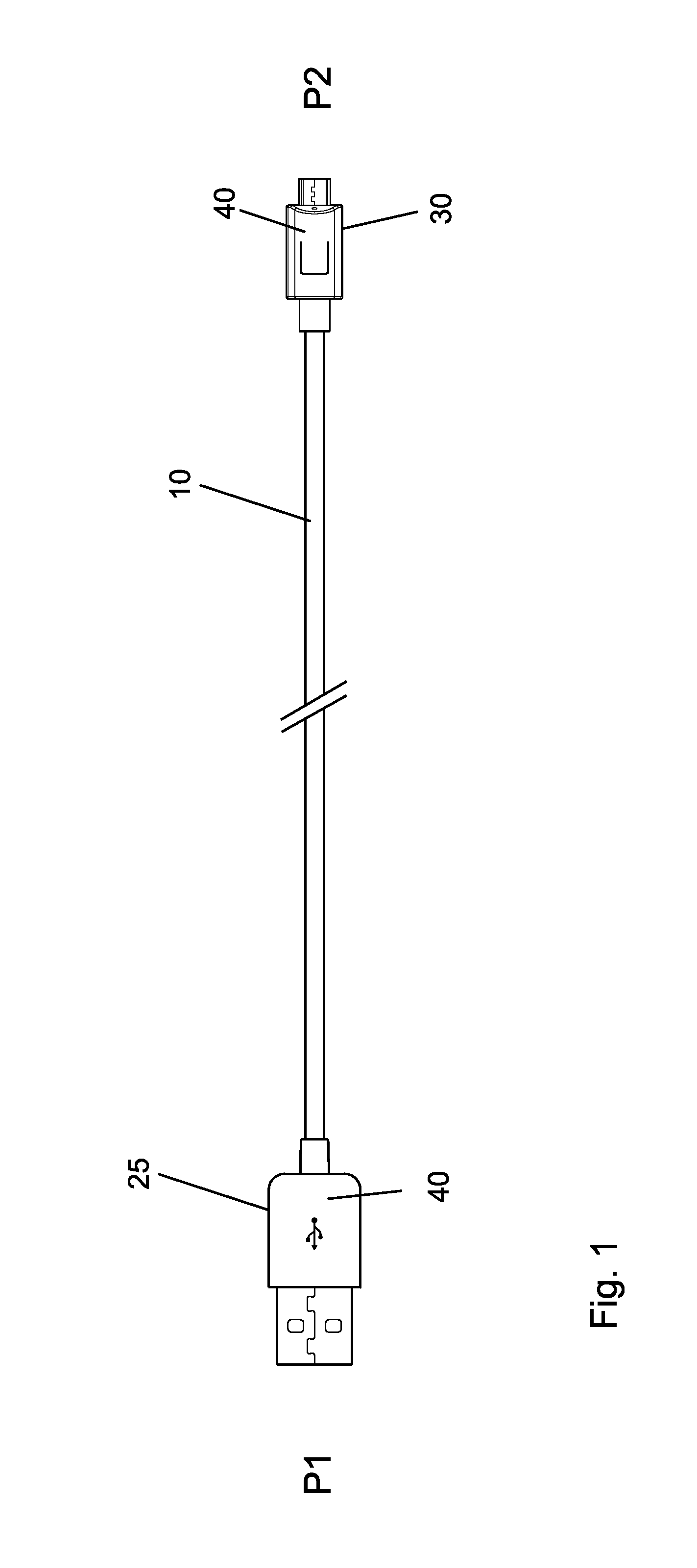
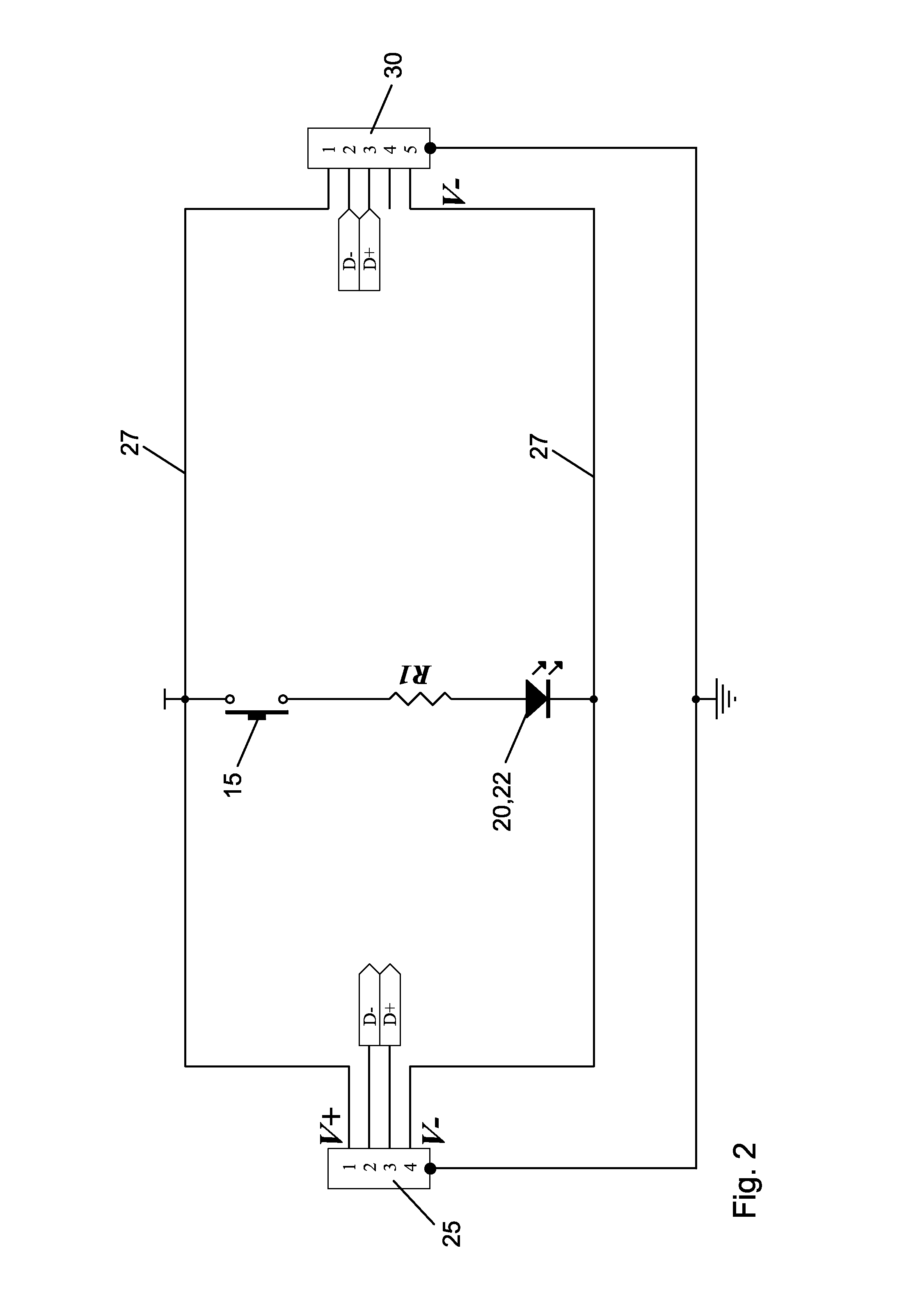
This patent describes a connection interface with a light for illuminating the connection area, minimizing light pollution and facilitating easy interconnection with reduced light pollution. The light is provided at the microUSB interface of the connector and is directed towards the insertion direction of the mating microUSB connector. The light is powered by a low-current LED circuit and is energizable via a switch. The switch can be activated by squeezing the connector overbody or by moving the switch handle. The illuminated interface cable provides a positive engagement characteristic and the illumination function is added with minimal additional cost and high reliability.

Problems solved by technology

A problem with the prior cables is that interconnecting the male cable connector interface to the electronic device female interface may be difficult as the interfaces are small and require relatively precise alignment prior to interconnection.
It may be particularly difficult to align for interconnection in poor lighting conditions and / or darkness as the female electronic device interface may be a recessed socket preventing alignment by touch.
However, a constantly illuminated cable may waste power and / or create undesireable illumination, for example in places / times where darkness may be preferred, such as a bedroom when another is person is sleeping.
Convenience, cost and / or reliability may be significant factors of commercial success in the consumer electronic market.

Method used


Image

  • Illuminated interface cable
  • Illuminated interface cable
  • Illuminated interface cable

Examples


Embodiment Construction

[0022]The inventors have recognized that a cable with a capacitive switch, activating a light emitting diode (LED) light illuminating the area of the connection interface whenever the capacitive switch surface is touched, also has the drawback of illuminating whenever the capacitive switch surface contacts other surfaces with suitable capacitive characteristics and / or may not be reliably actuated when the user fails to have suitable body capacitance, for example due to insulating coatings, a grounded environment and / or humidity pre-emptively inhibiting charging and / or dissipating any charge that may be present. Where a capacitive switch is applied to an interface cable, as the operator for a light or the like the capacitive switch may actuate by accident if accidentally shifted into contact with a suitable surface, turning on the light and disturbing those nearby.

[0023]As referenced herein, a mechanical switch is defined as a switch requiring physical movement of at least a portion ...


PUM


Abstract

An illuminated interface cable with a connector interface on at least one end. A light circuit including a light and a mechanical switch, the light circuit configured to energize the light upon actuation of the mechanical switch. The light and momentary switch coupled to the connector interface, the light oriented to illuminate an interconnection area of the connector interface. The light may be provided, for example, as a light emitting diode.

Description

BACKGROUND[0001]1. Field of the Invention[0002]This invention relates to power and / or data cables for electronic apparatus. More particularly, the invention relates to a power and / or data cable for electronic apparatus with an illuminated interconnection interface.[0003]2. Description of Related Art[0004]Electronic apparatus, particularly portable electronic devices such as cellular telephones, laptops and / or tablet computers utilize cables for power, charging and / or data exchange.[0005]A typical standardized interface for many electronic devices is the microUSB interface. A microUSB interface provides both power and data interconnections in a very small space, reducing the mating connector dimensions required on the electronic device and thereby enabling electronic devices that are smaller and therefore have increased portability.[0006]Electronic devices may require interconnection with the cable, for example for charging as a part of daily routine, often performed for example by t...

Claims


Application Information

Patent Timeline
IPC IPC(8): F21V33/00
CPCF21V33/0004H01R13/6641H01R13/70H01R31/065
Inventor MORROW, TERRELLCHRISTY, WILLIAMLOPOTKO, MARK WILLIAMWHETSTONE, CHRISTOPHER
Owner XENTRIS WIRELESS
Learn More