

Display carrier
a technology for carrying and storing objects, applied in the field of carrying objects, can solve the problem that the display is not necessarily tough against an external factor, and achieve the effect of safe carrying of objects
- Summary
- Abstract
- Description
- Claims
- Application Information
AI Technical Summary
Benefits of technology
Problems solved by technology
Method used
Image

Examples
first exemplary embodiment
[0026](First Exemplary Embodiment)
[0027](Description of a Structure)
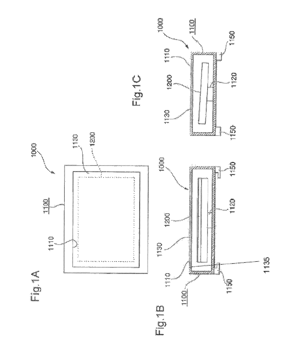
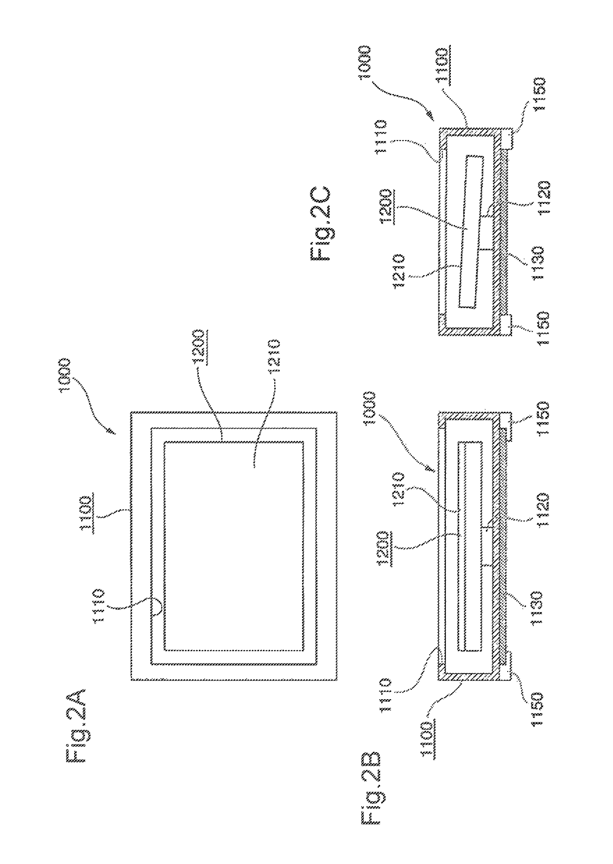
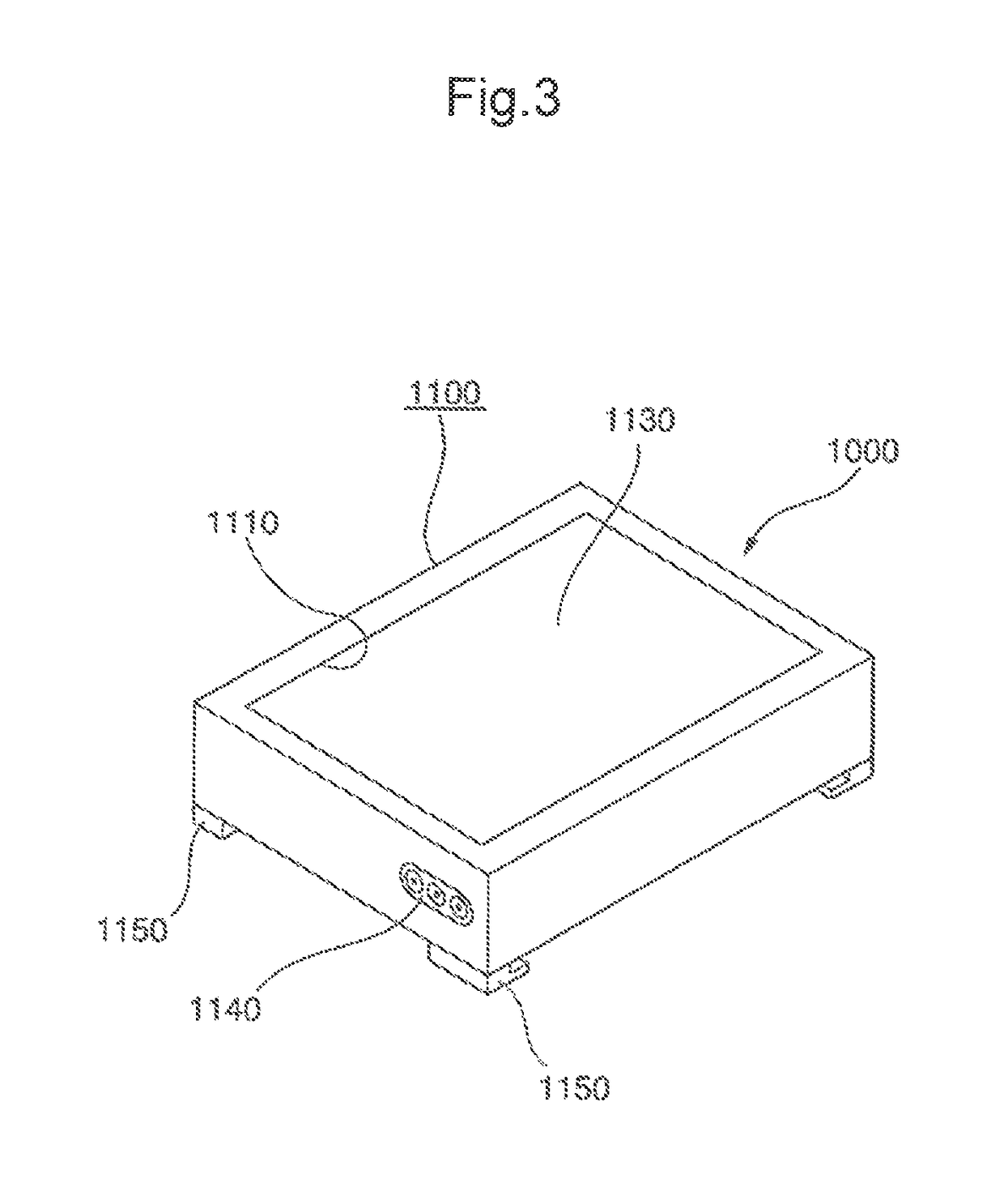
[0028]The first exemplary embodiment of the present invention will be described below with reference to FIGS. 1 to 5. A display carrier 1000 of this exemplary embodiment has a storage box 1100, a fixing member 1120 and a closing member 1130.
[0029]The storage box 1100 stores a display 1200 having a display screen 1210. The fixing member 1120 fixes the display 1200 inside the storage box 1100.
[0030]A window part 1110 for visually recognizing the display screen 1210 from outside is formed in a face of the storage box 1100 facing the display screen 1210 of the display 1200 which has been fixed. The closing member 1130 closes the window part 1110.
[0031]The display 1200 is a liquid crystal display or a plasma display of a panel shape, for example. The display screen 1210 is formed into a quadrangle shape (a rectangle, for example).
[0032]As shown in FIG. 1 and FIG. 2, the storage box 1100 is formed into a hollow structure ...
second exemplary embodiment
[0056](Second Exemplary Embodiment)
[0057]Each of FIG. 6 and FIG. 7 indicates a perspective view of a display carrier 2000 according to the second exemplary embodiment of the present invention. FIG. 6 is a perspective view of a state that the window part is closed, and FIG. 7 is a perspective view of a state that the window part is exposed. Meanwhile, FIG. 6 and FIG. 7 indicate the state that the display carrier 2000 is placed vertically.
[0058]The display carrier 2000 includes a pair of upper and lower closing members 2131 and 2132. The closing member 2131 is rotatably attached to the upper end part of the window part 1110 via a hinge mechanism 2110. The closing member 2132 is rotatably attached to the lower end part of the window part 1110 via the hinge mechanism 2110.
[0059]Further, as shown in FIG. 7, the display carrier 2000 includes a pair of right and left closing members 2133 and 2134. The closing member 2133 is rotatably attached to the right end part of the window part 1110 v...
third exemplary embodiment
[0067](Third Exemplary Embodiment)
[0068]FIG. 8 and FIG. 9 indicate perspective views of a display carrier 3000 according to the third exemplary embodiment of the present invention, respectively. FIG. 8 is a perspective view of a state that a window part is closed, and FIG. 9 is a perspective view of a state that the window part is exposed. Meanwhile, FIG. 8 and FIG. 9 indicate a state where the display carrier 3000 is placed vertically.
[0069]The structure of the display carrier 3000 is identical with the display carrier 2000 except for a part. Accordingly, an identical reference symbol is given to an identical component, and description about such components will be omitted.
[0070]In the display carrier 3000, an underside closing member 3110 is divided into two pieces: a first closing part 3111 and a second closing part 3112. The first closing part 3111 and the second closing part 3112 are rotatably connected with each other via the hinge mechanism 2110.
[0071]As shown in FIG. 9, the ...
PUM
 Abstract
Description
Claims
Application Information