Scanning unit and image display device

a scanning unit and image display technology, applied in the field of scanning units and image display devices, can solve the problems of increased power consumption, difficult mounting of large-sized displays, and eye stimulation by projection lights, and achieve the effects of reducing costs, adequate brightness, and high safety for eyes

Inactive Publication Date: 2012-04-03
PANASONIC CORP
View PDF24 Cites 0 Cited by
  • Summary
  • Abstract
  • Description
  • Claims
  • Application Information

AI Technical Summary

Benefits of technology

[0029]According to the present invention, the movable object moves in accordance with the angular velocity of the scan unit, thereby changing the reflecting state of the reflecting portion with respect to laser light. As a result, even when the scan speed of the scan unit lowers or the scan operation has come to a halt, the radiation power (energy density) of the laser light which is projected outside the image display apparatus can be decreased, thereby providing an image display apparatus which is highly safe for the eyes. According to the present invention, there is no need for sensors for detecting whether the scan operation of the mirror is normal or not and a control mechanism for blocking laser light or cutting supply of electric power to the laser light source when the scan operation is not normal. As a result, there is provided an image display apparatus which is capable of performing display with safety and adequate brightness, while realizing downsizing and cost reduction.
[0030]In one embodiment, the movable object moves in accordance with the angular velocity of the scan unit to cover at least a part of the reflecting portion, thereby decreasing the light amount of the laser light reflected by the reflecting portion.
[0031]In one embodiment, the movable object moves in accordance with the angular velocity of the scan unit to deform the reflecting portion, thereby increasing the degree of scattering of the reflected light from the reflecting portion.

Problems solved by technology

When a human comes into a projection light path between a projector for projecting an image onto a screen and the screen and turns his or her face toward the projecting side, there is a danger in that the projection light may stimulate his or her eyes.
Such a scanning-based laser projector displays an image by modulating the intensity of laser light, and thus is even more power-thrifty than any usual projector that uses two-dimensional image displaying devices, e.g., a liquid crystal panel or a DMD (Digital Micromirror Device).
Thus, large-scale displaying can be enjoyed even with a mobile phone or the like, in which a large-sized display would be difficult to be mounted.

Method used


Image

  • Scanning unit and image display device
  • Scanning unit and image display device
  • Scanning unit and image display device

Examples


embodiment 1

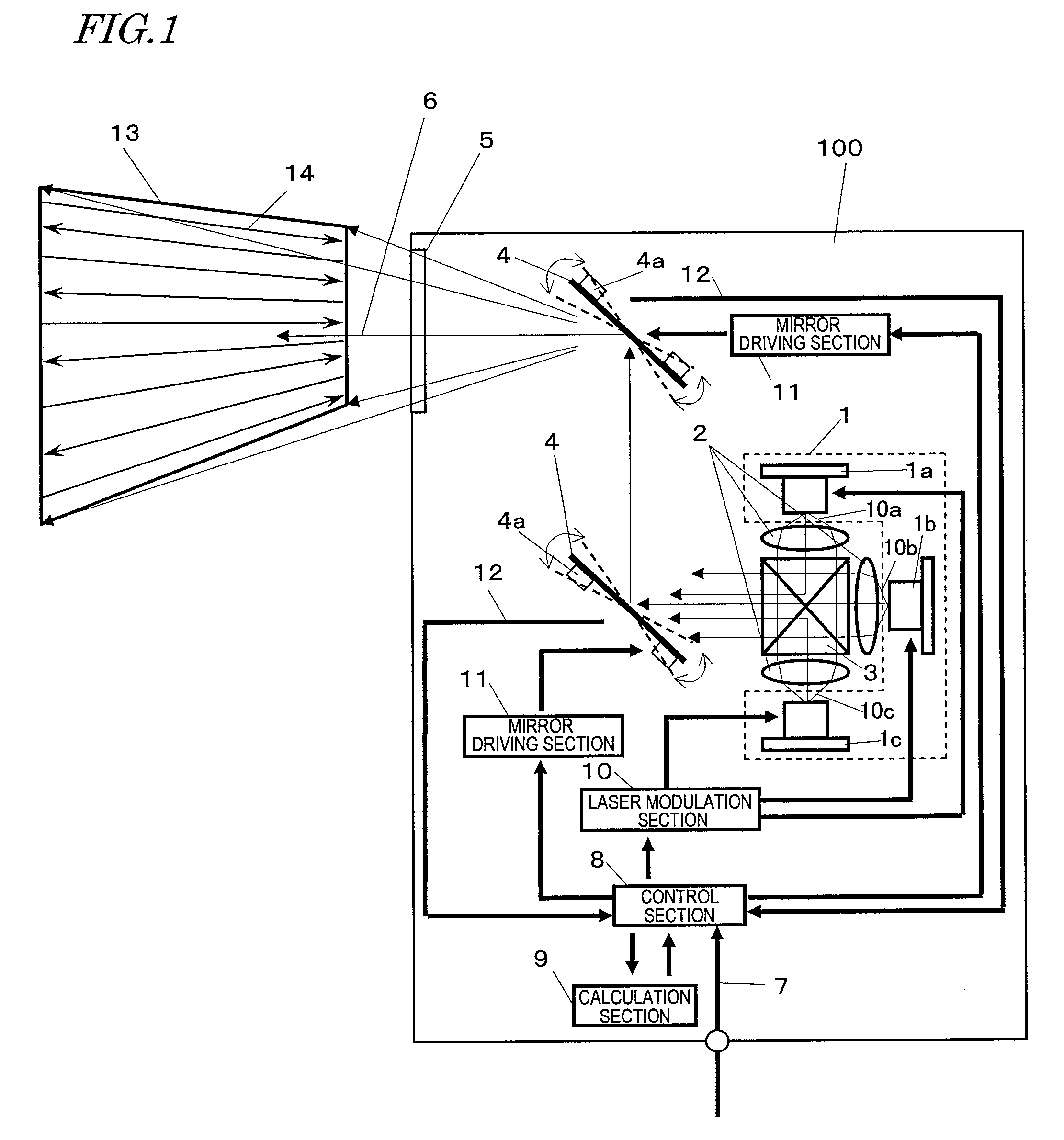
[0067]With reference to FIG. 1 to FIG. 9, a first embodiment of an image display apparatus and a scan unit according to the present invention will be described. First, FIG. 1 will be referred to. FIG. 1 is a diagram showing an image display apparatus 100 according to the present embodiment. The image display apparatus 100 displays an image on a screen or the like with at least a portion of projected laser light.

[0068]The image display apparatus 100 includes a light source 1 for outputting laser light 10a to 10c, collimating lenses 2, a dichroic prism 3, and scan units 4 for allowing the laser light 10a to 10c to be reflected and projected. The light source 1 outputs laser light of each color of n primary colors (where n is a natural number equal to or greater than 3). In this example, the light source 1 includes a light-emitting element 1a for outputting red laser light 10a, a light-emitting element 1b for outputting green laser light 10b, and a light-emitting element 1c for outputt...

embodiment 2

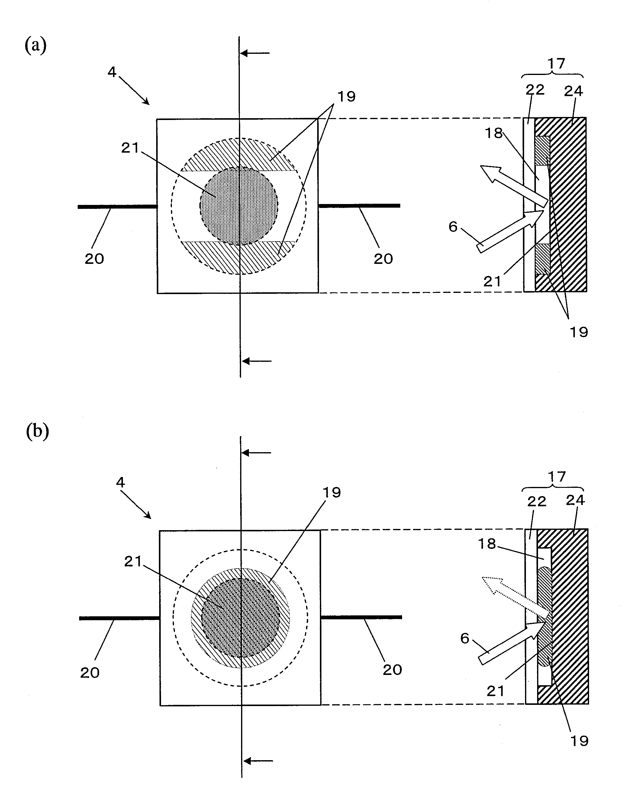
[0162]With reference to FIG. 10, a scan unit will be described in which a moving movable object 19 deforms a reflecting portion 21 to cause a change in the reflecting state (degree of scattering of reflected light) of the reflecting portion 21.

[0163]FIG. 10 is a diagram showing the scan unit 4 of the present embodiment. Each left-hand side diagram in FIG. 10 is a view showing the scan unit 4 from its reflection surface side, whereas each right-hand side diagram is a cross-sectional view of the scan unit 4. FIG. 10(a) shows the scan unit 4 when operating normally, whereas FIG. 10(b) shows the scan unit 4 when at halt.

[0164]In the example shown in FIG. 10, an enclosure portion 17 is formed by a base 24 and the reflecting portion 21. The base 24 and a reflecting portion 21 define a hollow portion 18 within the enclosure portion 17. The movable object 19 is enclosed in the hollow portion 18. A reflection surface of the reflecting portion 21 is positioned at the surface of the enclosure ...


PUM


Abstract

A scan unit according to the present invention is a scan unit including: a reflecting portion for reflecting laser light; and an enclosure portion having a movable object enclosed within a hollow, characterized in that the movable object moves in accordance with an angular velocity of the scan unit, thereby changing a reflecting state of the reflecting portion with respect to the laser light. In one embodiment, the movable object moves in accordance with the angular velocity of the scan unit to cover at least a part of the reflecting portion. In one embodiment, the movable object moves in accordance with the angular velocity of the scan unit to deform the reflecting portion.

Description

TECHNICAL FIELD[0001]The present invention relates to an image display apparatus for projecting laser light to display an image, and in particular to a technique of improving the safety of an image display apparatus.BACKGROUND ART[0002]When a human comes into a projection light path between a projector for projecting an image onto a screen and the screen and turns his or her face toward the projecting side, there is a danger in that the projection light may stimulate his or her eyes. Therefore, a method has been proposed in which a detection section for detecting the presence or absence of an object in the projection light path and a control section for controlling radiation power are provided in an image display apparatus, and when an object is detected in the projection light path, the radiation power is reduced to prevent danger.[0003]For example, Patent Document 1 discloses an image display apparatus which monitors a projection region with an electromagnetic radiation sensor, a ...

Claims


Application Information

Patent Timeline
Patent Type & Authority Patents(United States)
IPC IPC(8): G02B26/02
CPCG02B26/0816G02B26/101
Inventor OBI, HIROSHITOMITA, HIRONORIKUROZUKA, AKIRAKAJINO, OSAMU
Owner PANASONIC CORP
Why Eureka
Try Eureka