Substrate holding/rotating device, substrate processing apparatus including the same, and substrate processing method

a technology of holding/rotating device and substrate, which is applied in the direction of flexible article cleaning, cleaning process and apparatus, chemistry apparatus and processes, etc., can solve the problem of not being able to selectively open just a portion of the holding pin among the plurality of holding pins

Active Publication Date: 2019-01-29
DAINIPPON SCREEN MTG CO LTD
View PDF17 Cites 10 Cited by
  • Summary
  • Abstract
  • Description
  • Claims
  • Application Information

AI Technical Summary

Benefits of technology

[0010]Also, another object of the present invention is to provide a substrate processing apparatus and a substrate processing method by which a peripheral edge portion of a substrate can be processed satisfactorily without any unprocessed portions remaining.
[0030]With the present arrangement, the support portions of the respective movable pins are urged to one of either of the open position and the hold position by the first urging magnet and the second urging magnet. An arrangement that urges the support portions of the respective movable pins to one of either of the open position and the hold position can thereby be realized easily.
[0034]With the present arrangement, the first and second urging magnets can be moved up and down by moving the protective disk up and down. The first and second urging magnets thus do not have to be arranged separately in addition to an elevating / lowering unit arranged to move the protective disk up and down and simplification of device arrangement and cost reduction can thereby be achieved.
[0038]A protective disk, which is disposed between the rotary table and a position of substrate holding by the plurality of movable pins, is capable of relative up / down movement with respect to the rotary table between a lower position and an approach position approaching a lower surface of the substrate held higher than the lower position by the holding member, and is mounted to the rotary table so as to rotate around the rotational axis together with the rotary table, a first levitating magnet, mounted to the protective disk, a second levitating magnet, arranged in a non-rotating state and applying a repulsive force to the first levitating magnet, and a third relative movement unit, which makes the second levitating magnet and the rotary table move relatively to change a distance between the first levitating magnet and the second levitating magnet independently of each of the relative movement of the first moving magnet and the rotary table and the relative movement of the second moving magnet and the rotary table, may further be provided.
[0041]With the present arrangement, the processing liquid is supplied from the processing liquid supplying unit to a major surface of the substrate. The processing liquid supplied to the major surface of the substrate receives a centrifugal force due to rotation of the substrate and flows toward a peripheral edge portion of the substrate. The peripheral edge portion of the substrate is thereby liquid-processed by the processing liquid. With the present invention, it is possible to change positions of contact support of the substrate by the movable pins during rotation of the substrate. The peripheral edge portion of the substrate can thus be processed satisfactorily without any unprocessed portions remaining.
[0046]It is therefore possible to change the positions of contact support of the substrate by the movable pins in the processing liquid supplying step of supplying the processing liquid to the major surface of the substrate while rotating the substrate. The processing liquid can thus be supplied to an entirety of the peripheral edge portion of the substrate and the peripheral edge portion of the substrate can thereby be processed satisfactorily without any unprocessed portions remaining.

Problems solved by technology

However, with the magnet switching type substrate holding / rotating device described in Patent Document 1, the elevated / lowered magnet for switching between opening and closing of the movable pins is arranged to be non-rotating and it is therefore not possible to selectively open just a portion of the holding pins among the plurality of holding pins provided on the rotary table that is being rotated.

Method used


Image

  • Substrate holding/rotating device, substrate processing apparatus including the same, and substrate processing method
  • Substrate holding/rotating device, substrate processing apparatus including the same, and substrate processing method
  • Substrate holding/rotating device, substrate processing apparatus including the same, and substrate processing method

Examples


Embodiment Construction

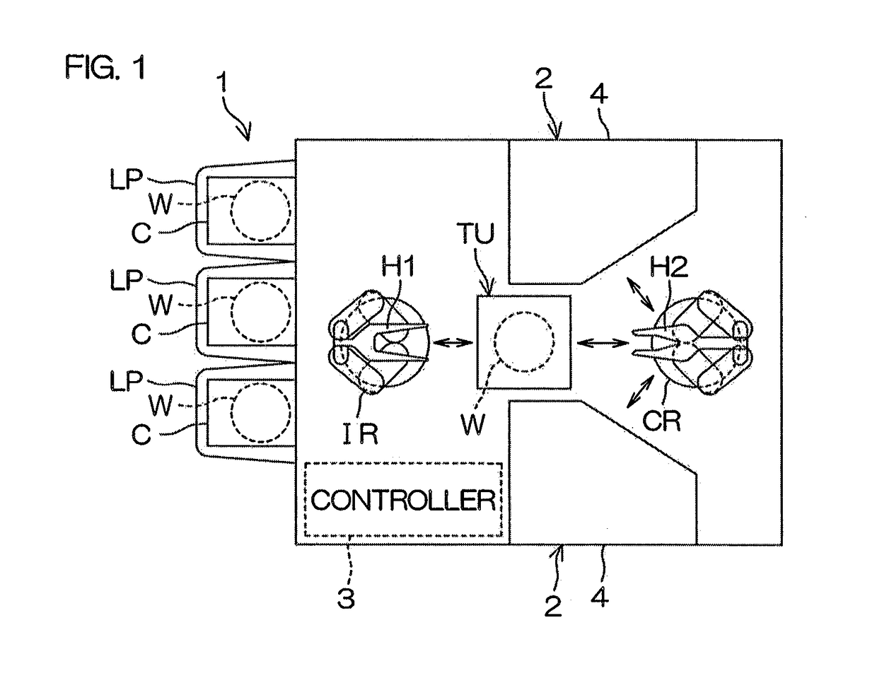
[0081]FIG. 1 is an illustrative plan view for describing a layout of an interior of a substrate processing apparatus 1 according to a first preferred embodiment of the present invention.

[0082]The substrate processing apparatus 1 is a single substrate processing type apparatus that processes disk-shaped substrates W, constituted of semiconductor wafers (semiconductor substrates), one at a time by a processing liquid or a processing gas. The substrate processing apparatus 1 includes load ports LP that hold a plurality of carriers C, a turnover unit TU that performs up / down turnover of the orientation of the substrate W, and a plurality of processing units 2 that process the substrates W. The load ports LP and the processing units 2 are disposed across an interval in a horizontal direction. The turnover unit TU is disposed on a transfer path of the substrates W that are transferred between the load ports LP and the processing units 2.

[0083]As shown in FIG. 1, the substrate processing a...


PUM


Abstract

A substrate holding / rotating device includes an urging unit, urging support portions of movable pins to either an open position or a hold position, first and second driving magnets, mounted in correspondence to respective movable pins of respective first and second movable pin groups and having mutually opposite magnetic pole directions, a first moving magnet, for urging the support portions of the first movable pin group to the other of either the open position or the hold position, and a second moving magnet, for urging the support portions of the second movable pin group to the other of either the open position or the hold position.

Description

BACKGROUND OF THE INVENTION[0001]1. Field of the Invention[0002]The present invention relates to a substrate holding / rotating device, a substrate processing apparatus including the same, and a substrate processing method. Examples of substrates to be held or substrates to be processed include semiconductor wafers, substrate for liquid crystal display devices, substrate for plasma displays, substrates for FEDs (field emission displays), substrates for optical disks, substrates for magnetic disks, substrates for magnet-optical disks, substrates for photomasks, ceramic substrates, substrates for solar cells.[0003]2. Description of Related Art[0004]US2013 / 0152971 A1 discloses a rotating type substrate holding / rotating device that includes a rotary table rotatable around a rotational axis aligned with a vertical direction, a rotation driving unit that rotates the rotary table around the rotational axis, and a plurality (for example, four) of holding pins disposed on the rotary table and ...

Claims


Application Information

Patent Timeline
Patent Type & Authority Patents(United States)
IPC IPC(8): H01L21/687H01L21/67B08B11/02
CPCH01L21/68742B08B11/02H01L21/68728H01L21/67051H01L21/67028
Inventor KABA, HIROMICHITAKI, AKIHIKO
Owner DAINIPPON SCREEN MTG CO LTD
Why Eureka
Try Eureka