Power supply belt containing flexible battery and power generation means for supplying power to portable electronic devices, including wearable devices
a technology of flexible batteries and power supply belts, applied in the direction of cell components, cell component details, transportation and packaging, etc., can solve the problems of high-capacity batteries, large and heavy, and the expected weight and size of terminals and wearable devices to be reduced
- Summary
- Abstract
- Description
- Claims
- Application Information
AI Technical Summary
Benefits of technology
Problems solved by technology
Method used
Image
Examples
embodiment 1
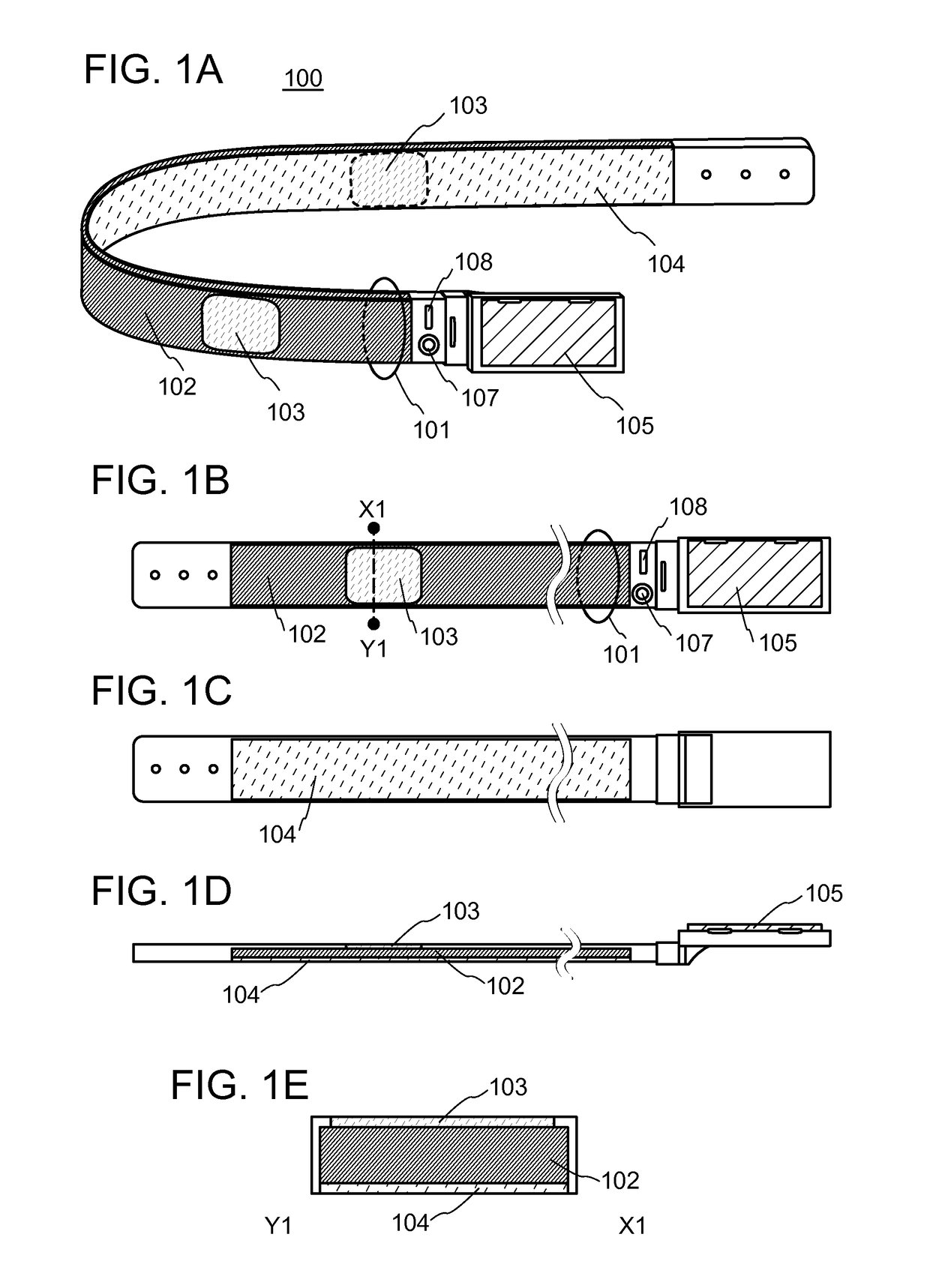
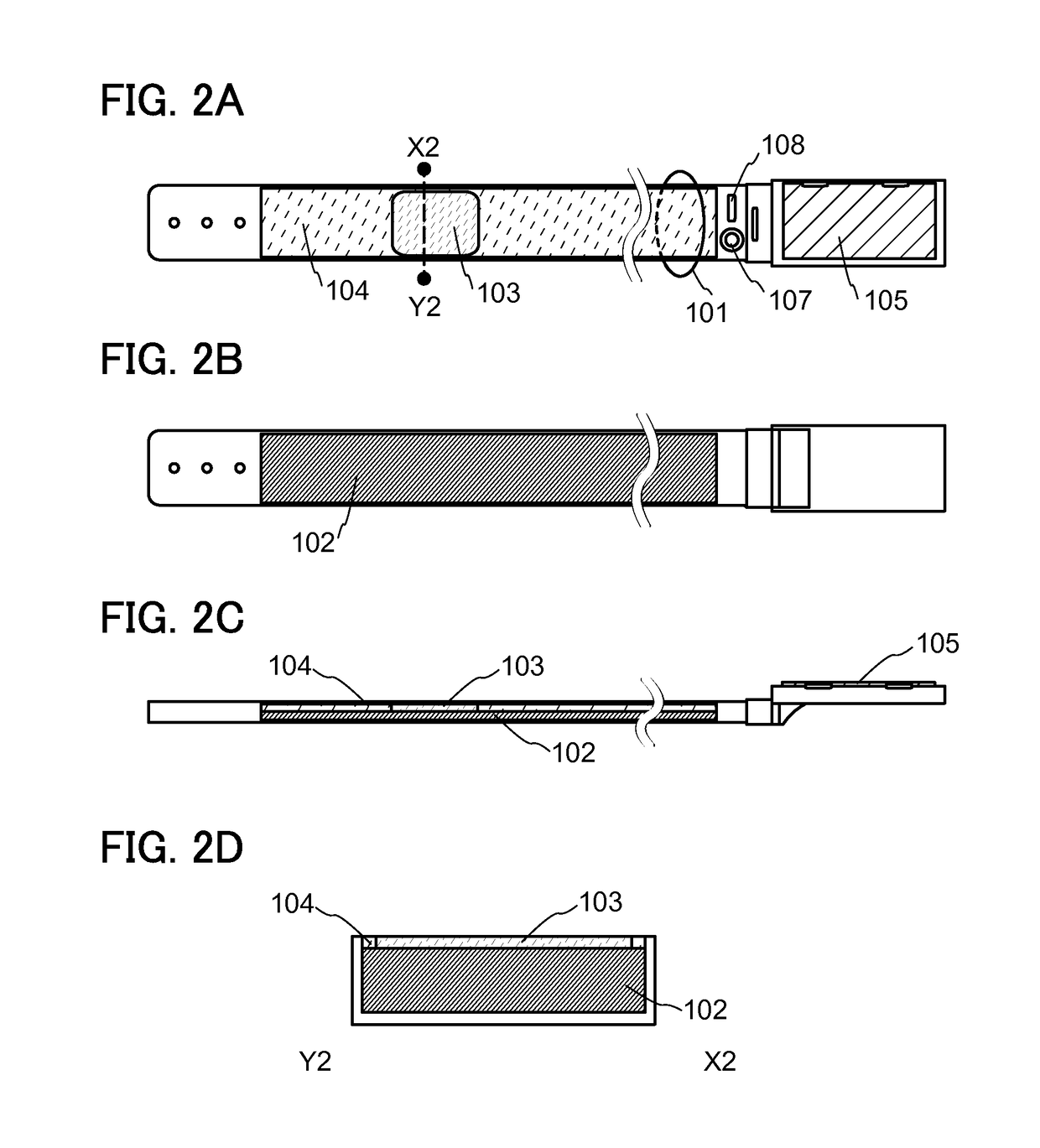
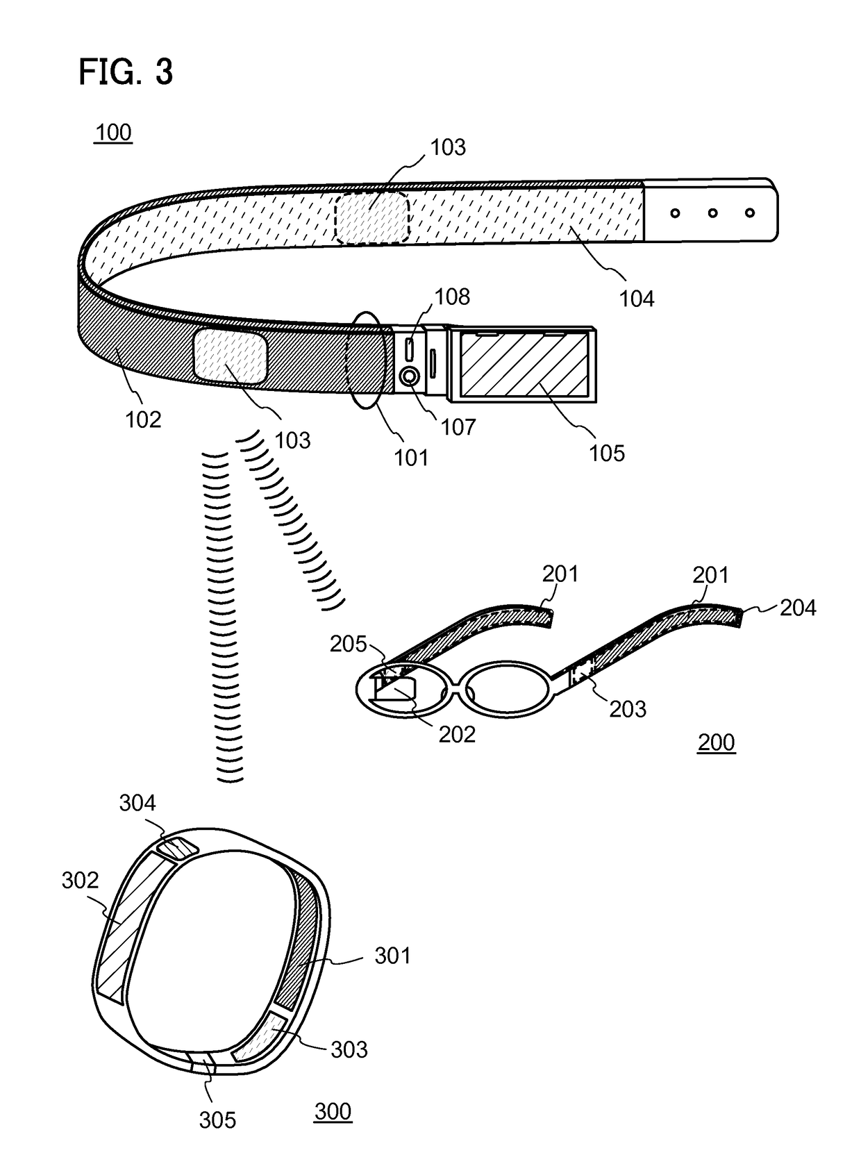
[0032]In this embodiment, a secondary battery module and a power feeding system according to one embodiment of the present invention are described using FIGS. 1A to 1E, FIGS. 2A to 2D, and FIG. 3.
[0033]First, a secondary battery module 100 is described. FIG. 1A is a perspective view illustrating the secondary battery module 100 which is curved. FIG. 1B is a front view of the secondary battery module 100. FIG. 1C is a rear view of the secondary battery module 100. FIG. 1D is a top view of the secondary battery module 100. FIG. 1E is a cross-sectional view taken along the line X1-Y1 in FIG. 1B.
[0034]The secondary battery module 100 includes a secondary battery 102 and a power transmitting device 103. The secondary battery module 100 preferably includes a power generating device 104. The secondary battery 102, the power transmitting device 103, and the power generating device 104 are stored in a belt portion 101. The belt portion 101 preferably includes a display portion 105. The displ...
embodiment 2
[0054]In this embodiment, other examples of the secondary battery module and power feeding system according to one embodiment of the present invention are described using FIGS. 4A and 4B and FIGS. 5A to 5C2.
[0055]In Embodiment 1, the examples of using the glasses-type device 200 and the wristband-type device 300 as the electronic devices to which electric power is transmitted from the secondary battery module 100 are described. In the power feeding system of one embodiment of the present invention, electric power can be transmitted from the secondary battery module 100 to other electronic devices having any of a variety of shapes or functions.
[0056]For example, as illustrated in FIG. 4A, electric power can be transmitted from the secondary battery module 100 to a headset-type device 401. The headset-type device 401 includes a microphone portion 401a, a flexible pipe 401b, and an earphone portion 401c. The flexible pipe 401b or the earphone portion 401c includes a secondary battery a...
embodiment 3
[0067]In this embodiment, a specific structure and material of the secondary battery 102 which can be included in the secondary battery module 100 according to one embodiment of the present invention are described using FIG. 6, FIGS. 7A and 7B, and FIGS. 8A and 8B. In this embodiment, an example where one of a positive electrode and a negative electrode is covered with a bag-like separator will be described below.
[0068]FIG. 6 is a perspective view showing an appearance of the secondary battery 102. FIG. 7A is a cross-sectional view taken along the dash-dot line A1-A2 in FIG. 6. FIG. 7B is a cross-sectional view of a portion indicated by the dash-dot line B1-B2 in FIG. 6.
[0069]The secondary battery 102 of one embodiment of the present invention includes a positive electrode 511 covered with the separator 503, a negative electrode 515, and an electrolyte solution 504 in an exterior body 507. In the example in FIG. 6 and FIGS. 7A and 7B, the secondary battery includes one positive elec...
PUM
| Property | Measurement | Unit |
|---|---|---|
| thickness | aaaaa | aaaaa |
| particle diameter | aaaaa | aaaaa |
| electric conductivity | aaaaa | aaaaa |
Abstract
Description
Claims
Application Information
 - R&D
- Intellectual Property
- Life Sciences
- Materials
- Tech Scout
- Unparalleled Data Quality
- Higher Quality Content
- 60% Fewer Hallucinations
Browse by: Latest US Patents, China's latest patents, Technical Efficacy Thesaurus, Application Domain, Technology Topic, Popular Technical Reports.
© 2025 PatSnap. All rights reserved.Legal|Privacy policy|Modern Slavery Act Transparency Statement|Sitemap|About US| Contact US: help@patsnap.com


