Vehicular air-conditioning device

a technology of air conditioner and auxiliary unit, which is applied in the direction of indirect heat exchanger, light and heating apparatus, transportation and packaging, etc., can solve the problems of damage to the fins and tubes, adverse assembly effect, etc., and achieve the effect of convenient and reliable assembly

Active Publication Date: 2019-02-12
MAHLE INT GMBH
View PDF17 Cites 1 Cited by
  • Summary
  • Abstract
  • Description
  • Claims
  • Application Information

AI Technical Summary

Benefits of technology

[0005]A general object of the present invention is to provide a vehicular air conditioner, which enables a heat exchanger to be assembled easily and reliably with respect to an air conditioner casing.
[0011]Consequently, when the heat exchanger is assembled in the interior of the air conditioner casing, by carrying out assembly thereof while the side surfaces of the rails of the heat exchanger are made to abut against the guides formed in the air conditioner casing, since the heat exchanger can be guided along the guides while in surface contact toward the inner side in the insertion direction from the insertion opening, inclination of the heat exchanger with respect to the insertion direction can be prevented, and the heat exchanger can easily and reliably be assembled at a predetermined position in the interior of the air conditioner casing. Further, since inclination of the heat exchanger upon assembly thereof can be avoided, the tubes, etc., that constitute the heat exchanger are prevented from becoming damaged by coming into contact with the air conditioner casing.

Problems solved by technology

As a result, it is essential for assembly to be performed while an operator corrects the inclination of the evaporator toward the predetermined direction of insertion, and ease of assembly is adversely affected.
Further, by subjecting the evaporator to inclination, fins and tubes thereof, which are exposed to the exterior, tend to come into contact with the air conditioner casing and other members, leading to a concern that damage to the fins and tubes may occur.

Method used


Image

  • Vehicular air-conditioning device
  • Vehicular air-conditioning device
  • Vehicular air-conditioning device

Examples


Embodiment Construction

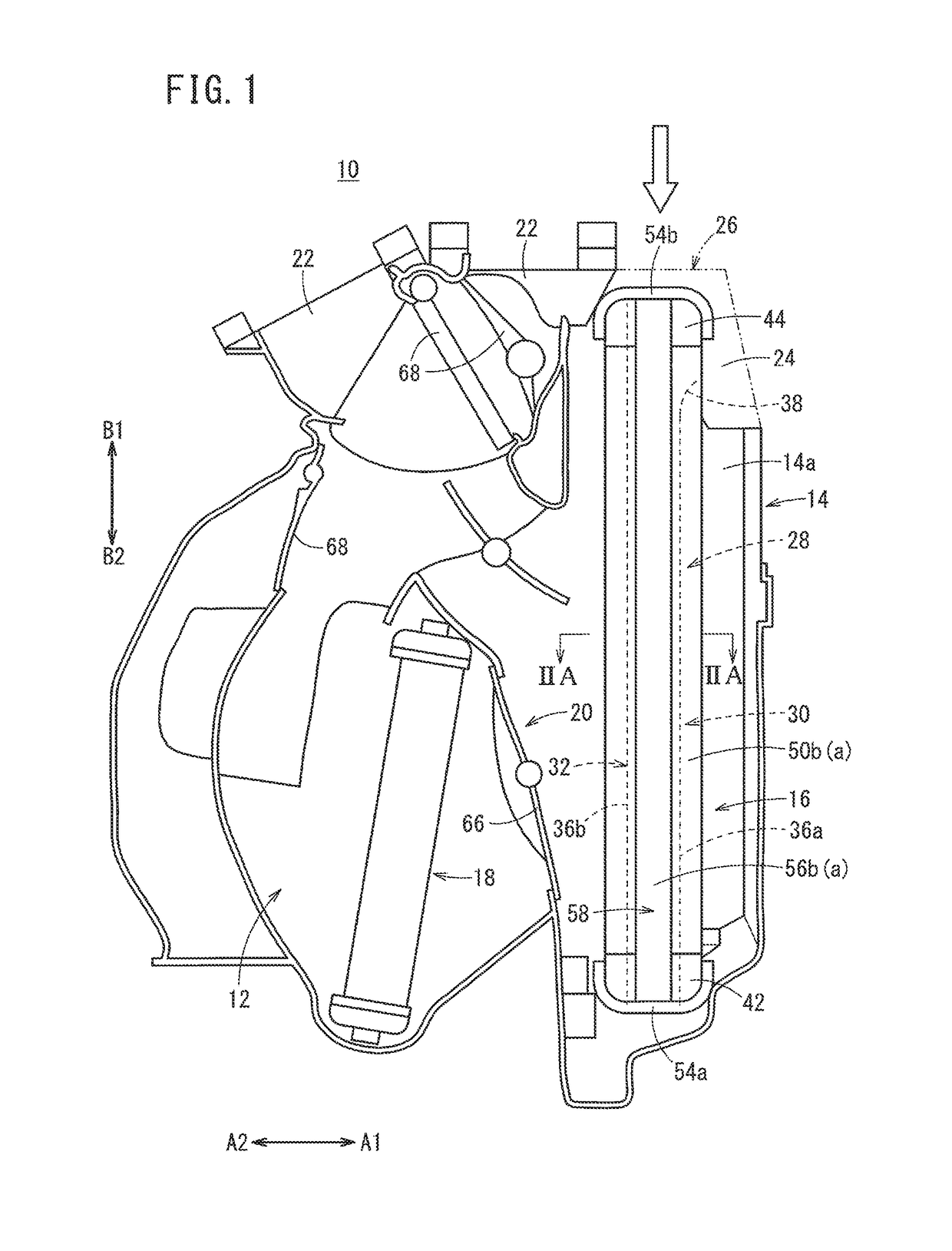
[0019]As shown in FIG. 1, a vehicular air conditioner 10 includes an air conditioner casing 14 constituted by respective airflow passages 12, an evaporator (heat exchanger) 16 arranged in the interior of the air conditioner casing 14 for cooling the air, a heater core 18 for heating the air, and a damper mechanism 20, which operates to switch the flow of air that flows through the respective passages 12.

[0020]The air conditioner casing 14 is formed in a box shape from a resin material, and plural blower openings 22, which communicate with the respective passages 12 and blow air toward the front window or in the vicinity of the face of a vehicle occupant, are formed in an upper portion of the air conditioner casing 14. The right side (in the direction of the arrow A1) of the vehicular air conditioner 10 shown in FIG. 1 will be referred to as a front side of the vehicle, and the left side (in the direction of the arrow A2) will be referred to as a rear side of the vehicle.

[0021]Furthe...


PUM


Abstract

In this vehicular air-conditioning device, an inner wall surface along a width direction of an air-conditioning casing is provided with guide portions each extending in a vertical direction. The guide portions are recessed on the outside in the width direction, forming recesses with respect to the inner wall surface. When an evaporator is inserted from above the air-conditioning casing and assembled inside, second seal portions of side plates disposed on side surfaces of the evaporator are respectively inserted into the guide portions, whereby the evaporator is guided along the vertical direction. The guide portions further include an entry portion disposed at an upper end portion of a first guide wall and expanding in a direction away from a second guide wall. Thus, the evaporator can be inserted into the air-conditioning casing from above in a preferable manner.

Description

TECHNICAL FIELD[0001]The present invention relates to a vehicular air conditioner (vehicular air-conditioning device) that is mounted in a vehicle for adjusting the temperature in the interior of a vehicle cabin by blowing air into the vehicle cabin, the temperature of the air being adjusted by a heat exchanger.BACKGROUND ART[0002]Heretofore, a vehicular air conditioner, which is mounted in a vehicle, takes in interior and exterior air by a fan into an air conditioner casing having an airflow passage in the interior thereof, and after mixing chilled air, which is cooled by an evaporator type of cooling means, and heated air, which is heated by a heater core type of heating means, by operation of a damper inside the air conditioner casing at a desired mixing ratio, the mixed air is made to pass from a plurality of openings disposed in the casing and through an outlet port, and is blown out into the vehicle cabin interior, whereby adjustment of temperature and humidity is carried out ...

Claims


Application Information

Patent Timeline
Patent Type & Authority Patents(United States)
IPC IPC(8): B60H1/00B60H1/32F28F9/013F28D1/053F28D21/00
CPCB60H1/00521B60H1/3227F28F9/0132F28D1/05375F28D2021/0085B60H2001/00635
Inventor CHIBA, SHINYA
Owner MAHLE INT GMBH
Why Eureka
Try Eureka